Week - 4
Aim:
- Implement control logic of a Washing machine using stateflow by following the given sequence and conditions.
- Gear shift logic according to the speed range given for individual gears.
Software used: MATLAB R2020a.
Description:
Control logic:
It is the part of a controller that defines how a reactive system responds to events or conditional changes and in any model with numerus operations to be operated automatically the design should have a proper logic so that all operations are carried out properly at required time, control logic helps in carrying out the operations accordingly.
Stateflow:
It is a graphical environment within Simulink canvas that allows us to design and simulate decision logic for supervisor control, task scheduling, and fault management applications. Using Stateflow it becomes easy to provide logic for any particular operation in a Simulink model. Graphical animation enables us to analyse and debug logic while it is being executing. Edit-time and run-time checks ensure design consistency and completeness before implementation.
1. Washing machine:
It is machine that helps in washing clothes.
These machines may be Semi-automatic or fully automatic.
The steps a washing machine follows or is being programmed for washing are as follows,
- Filling water.
- Soaking
- Washing
- Spinning and
- Drying.
Sequence and conditions to be followed:
- If the power supply is available, the system gets activated
- If the Water supply is not available, stop the process & indicate through LED
- Soaking time should be 200s followed by Washing time of 100s.
- Then rinsing happens for next 20s & dryer runs for 50s
- After all the processes have completed turn on the finished LED.
Simulink model:
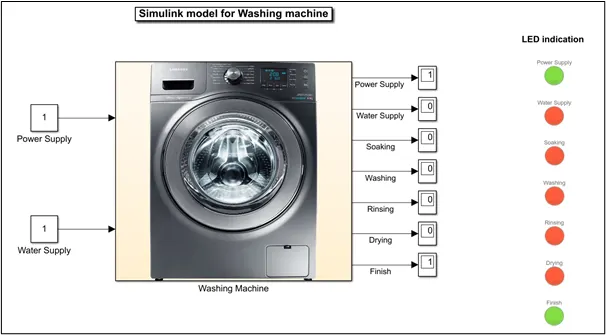
Simulink model construction:
- I’ve used two constant blocks as input one indicates Power supply and another indicates Water supply. If 1 is given as input to any constant block the supply (Water or Power) is ON and if input is 0 then, there is no supply (Water or Power).
- These constant blocks are connected to the Chart block (Washing machine) within which the control logic is prepared using Stateflow logic control.
- The output from the Chart block is connected to display block which indicates, ‘1’ if the process is running or supply is provided & ‘0’ if the process is turned off or supply is cut off.
- Used LAMP blocks as LEDs for indication of input status and process status. As shown in below snap where green indicates supply is being provided or process is turned ON & red indicates no supply or process has been completed.
Stateflow control logic implementation:
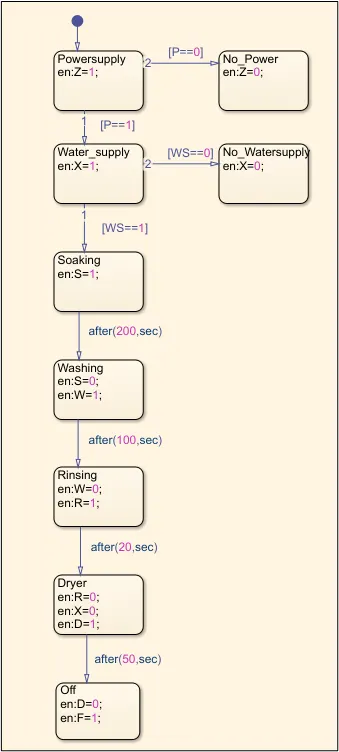
Above is the snap of the stateflow control logic of washing machine as per given conditions.
The abbreviations used in stateflow for input and output are defined in ‘Symbols pane’ tab under Simulation bar.
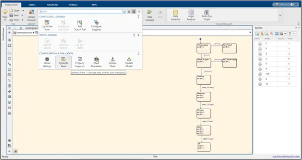
Following are the explanation of each state from the Stateflow control logic prepared for washing machine,
Power supply:
When the input is provided to the Stateflow chart first block (Power supply), it analyses and if there is no supply of power then there will be no activation of water supply block and no further operations will be carried out and LED turns red if there is no supply and turns green if supply is given.
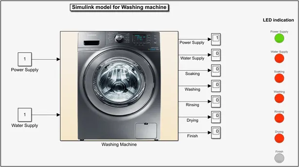
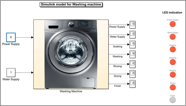
Water supply:
After assuring that there is power supply (Z=1) the supply of water for the system begins and further operations will be carried out with LED indicating green colour and if there no supply of water the LED turns red as shown below.
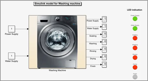
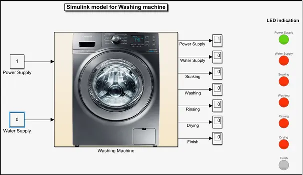
Soaking:
This process begins with supply of water and is carried for 200 seconds. The LED will be turned green during this process as shown in below snap.
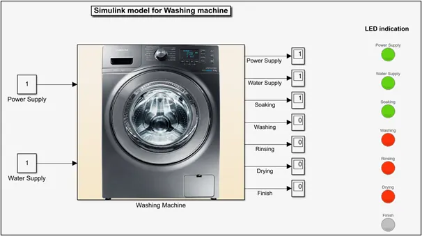
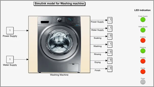
Washing:
This process is carried out for 100 seconds after soaking is completed. During this state the LEDs turn red for soaking and green for washing as shown in below snap.
Rinsing:
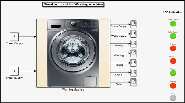
This process is carried out for 20 seconds after completion of washing. During this state the LEDs turn red for washing and green for rinsing as shown in below snap.
Drying:
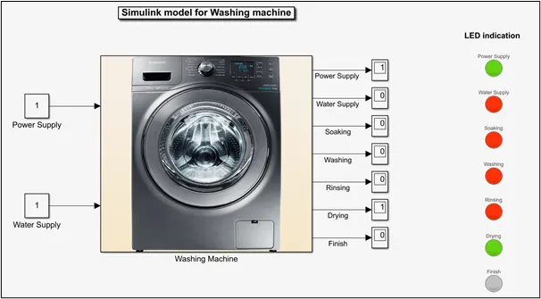
This is the last step of washing process which is carried out for 50 seconds after completion of rinsing process. The water supply will be turned off in this state and LEDs turn red for water supply and rinsing and green for Drying as shown in below snap.
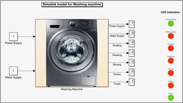
Finally, after completion of all the process the ‘Off’ state will be activated. LEDs turn red for all except power supply and finish as shown in below snap.
2. Gear shift:
Vehicles need a transmission to transfer the power from the engine to the drive shaft and the differential to let the wheels turn. The transmission varies the torque, the speed and the direction by changing the transmission ratios and enables the car to start with a high torque. In automobiles transmission may be automatic or manual.
Manual transmission, as name indicates the gears should be shifted manually after crossing certain speed limit.
Automatic transmission, here gears are shifted automatically by analysing the speed limits automatically through a logic using which this was designed. Following are the types of automatic transmission,
- Hydraulic automation transmission.
- Continuously variable transmission.
- Automated manual transmission.
- Dual-clutch transmission.
Given condition:
|
Speed Range(kmph) |
Gear number |
|
0 to 15 |
1 |
|
16 to 25 |
2 |
|
26 to 40 |
3 |
|
41 to 60 |
4 |
|
Above 61 |
5 |
Simulink Model:
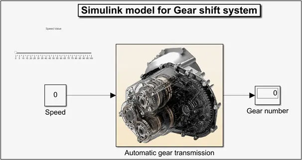
- I’ve used Slider block as throttle for varying the speed, it is connected to the constant block (named Speed).
- The constant block is connected to the Chart block (Automatic gear transmission) within which the control logic is prepared using Stateflow control logic.
- The output from the Chart block is connected to display block for indication of gear numbers.
Stateflow control logic implementation:
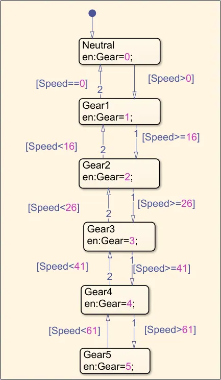
Above is the snap of the Stateflow control logic for shifting gears according to the given speed threshold for individual gear.
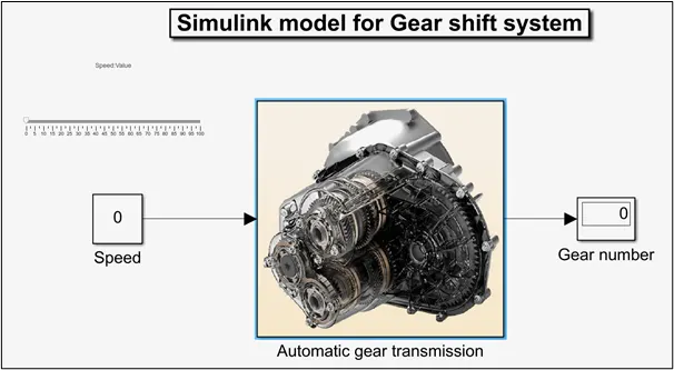
Neutral state is activated and ‘0’ will be displayed in the display block in Simulink canvas if speed is 0kmph as shown in below snap. The conditions for the transition from one state to another is written within square brackets along transition lines.
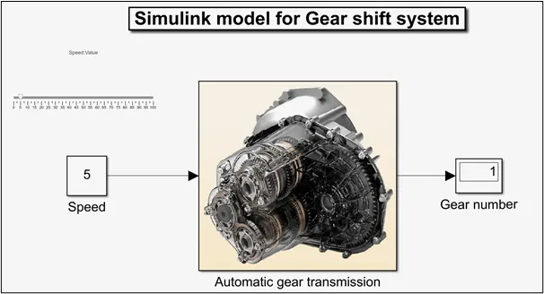
Gear1 state is activated and ‘1’ will be displayed in the display block in Simulink canvas if speed is >0kmph (at 0kmph vehicle is in neutral mode) as shown in below snap.
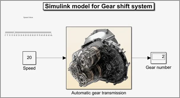
Gear2 state is activated and ‘2’ will be displayed in the display block in Simulink canvas if speed is `>=`16kmph as shown in below snap.
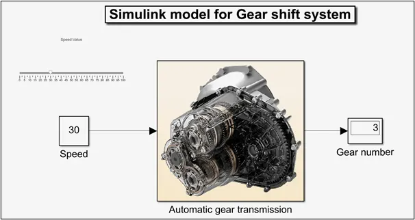
Gear3 state is activated and ‘3’ will be displayed in the display block in Simulink canvas if speed is `>=`26kmph as shown in below snap.
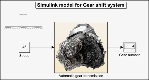
Gear4 state is activated and ‘4’ will be displayed in the display block in Simulink canvas if speed `>=`40kmph as shown in below snap.
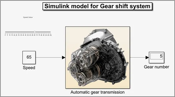
Gear5 state is activated and ‘5’ will be displayed in the display block in Simulink canvas if speed >61kmph as shown in below snap.
The conditions are also given for shifting of gears during decelaration accordingly.
Conclusion:
- Control logic using Stateflow was implemented to the ‘Washing machine’ model with satisfying the sequence of operation and the conditions provided.
- Gear shift control logic using stateflow was implemented and it is observed that gears are shifted according to the speed range given for each gears.