Week - 4
- Washing machine has been simulated using stateflow logic.
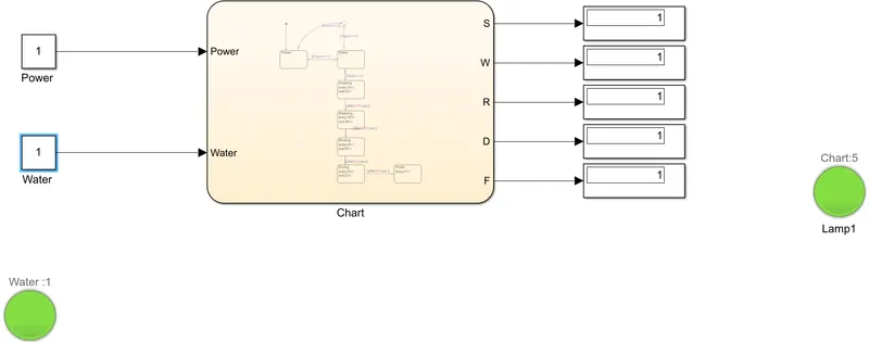
Constant block has been used as power & water supply input for chart. It is switched on & off by 1 & 0 values respectively. Control logic has been implemented in chart.
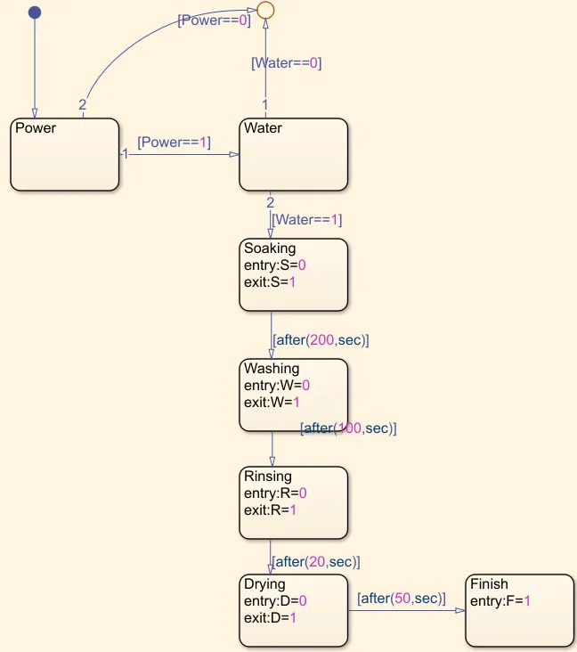
Default transition points to power, which is checked for its value. If it is on, water supply is checked. If any of them is off, it points to the junction and LED is turned red. If both of them are on, soaking happens for 200 seconds followed by washing for 100 seconds followed by rinsing for 20 seconds and drying for 50 seconds.
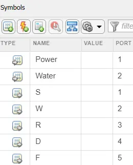
These states are implemented by using output signals S, W, R, D & using 0 as entry state while 1 as exit state. After this process is completed, it goes to finish state, represented by F with value 1. The LED turns green when the process completes.
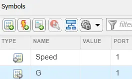
- Simulink model for speed and gear has been made. Constant block has been used to give speed as input to stateflow logic and display has been used to observe the gear output.
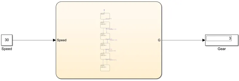
Stateflow logic has been set by matching the speed with gear. Speed greater than 15 is gear 2 and greater than 25 is gear 3 and so forth. Gear represented by G is the output of each state.
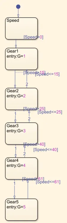
Display shows correct gear for different speeds demonstrating the correctness of stateflow logic.