Week -2
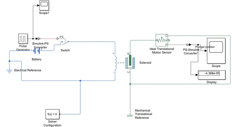
- Simulink model of a doorbell has been created using blocks like pulse generator, switch, battery, solenoid and ideal translational motion sensor. As per the requirements, a switch has been created which remains closed for 2 seconds. For this, block switch and pulse generator has been used.
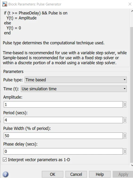
Amplitude of pulse generator is set at 1. Period of the signal is 4 seconds. Pulse width is for 50% of the period, so that makes it 2 seconds.
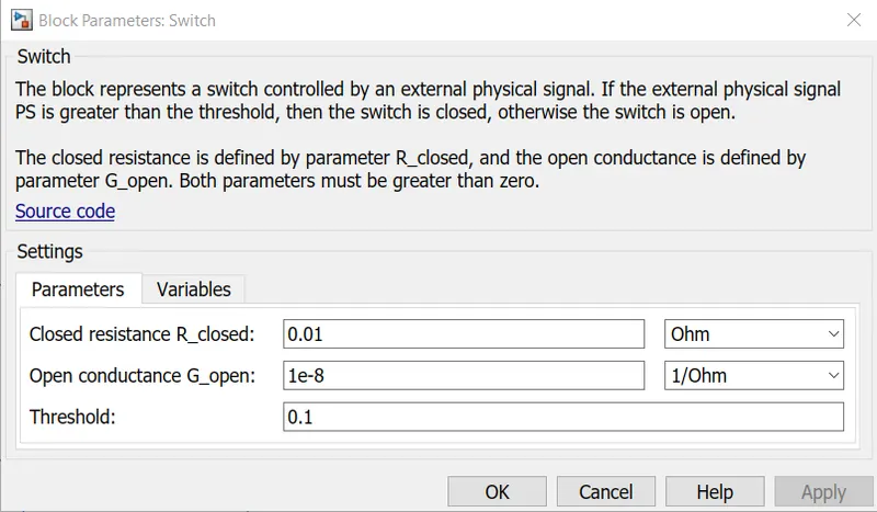
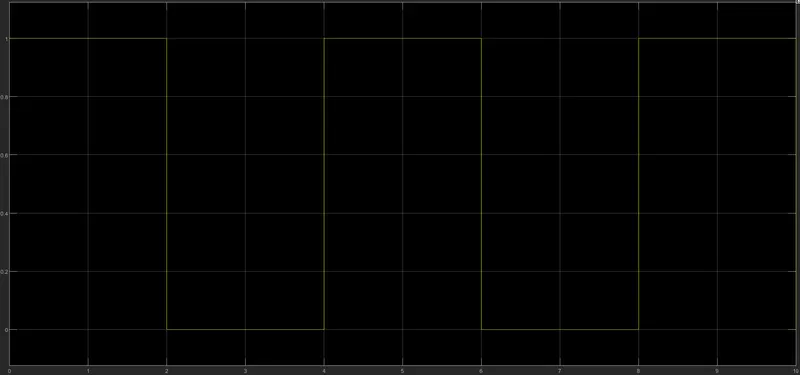
Threshold of the switch is set to 0.1, so it remains closed for 2 seconds and open for next 2 seconds, as the amplitude of pulse is 1. Battery is connected to switch to give it power and a complete electrical circuit has been simulated using electrical reference and solver configuration.
Solenoid block has been added which simulates a bell with a plunger. To observe the movement of plunger, ideal translational motion sensor is connected to the electromagnet. A display and scope are connected to motion sensor at its P port to obtain its position reading.
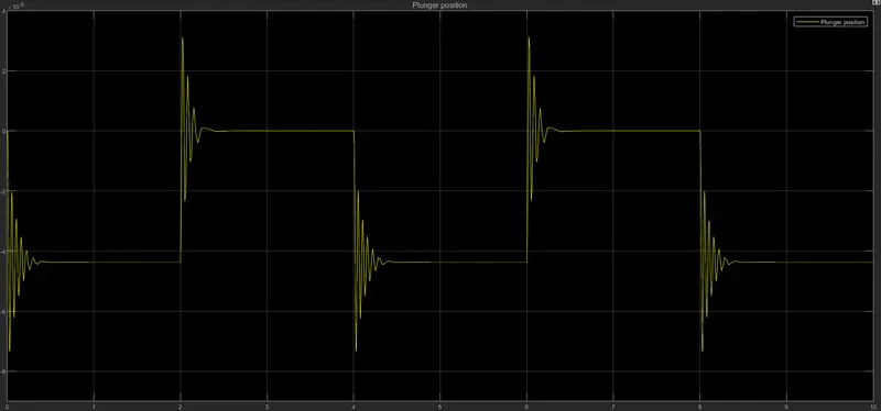
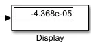
Results from scope & display are obtained as above. We can see the movement of plunger for the duration when switch is closed. Plunger moves to 4*10^-5m for 2 seconds and shows an oscillating behavior at the beginning of pulse. Display also reflects the corresponding result. The desired results show the correctness of the simulation and successfully demonstrate a bell action.
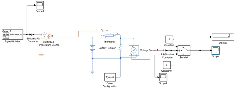
- Simulink model of heater & fan has been created by using controlled temperature source, signal builder, thermistor, switch and other blocks. To simulate the temperature of heater, signal builder has been used. For first 10 seconds, signal value is 20, then for next 20 seconds, it is at 27 and for the rest of 20 seconds, it is at 23.
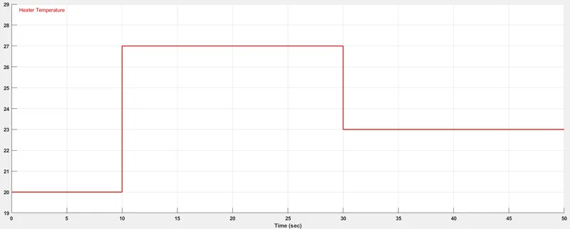
This signal is translated as temperature in degree Celsius by controlled temperature source. It is connected to thermistor, which has its resistance dependent on temperature. Reference temperature of thermistor is set at 25 deg Celsius. To make a complete electrical circuit, it is connected to battery, electrical reference and resistor. Voltage sensor is connected in parallel to resistor to take its voltage reading. Reading obtained from it is symmetrical to input signal.
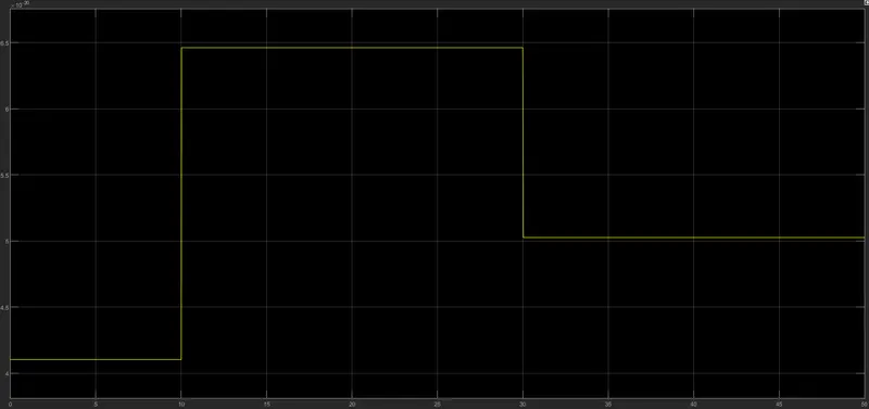
A switch has been used to simulate the fan on-off signal. Threshold of 6*10^-5 has been set corresponding to 25 deg Celsius. Heater above this temperature results in fan on and below it will be off. Result is obtained on a scope & display.
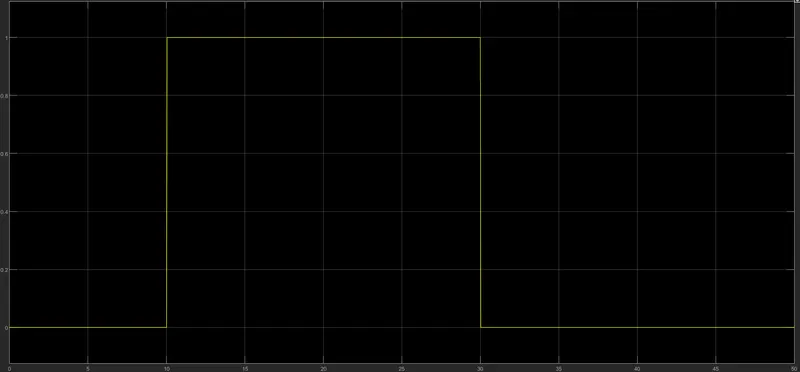
As we can see from the graph, fan is for first 10 seconds, turn on for the next 20 seconds and is off for the last 20 seconds as per the conditions set. Obtaining desired results showcase the accuracy of the model.