Project
Aim: This is a model of a Baja All-Terrain Vehicle (ATV). ATV is an off-road vehicle which is light and agile. Baja is an international collegiate competition for building ATV. This is a prebuild model on mathworks website. Major parts of this model consist of engine, continuously variable transmission (CVT) and vehicle body with their inputs and outputs. Goal of this project is to study ATV by running this model.
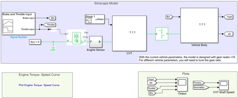
Throttle is fed to the engine using a signal builder.
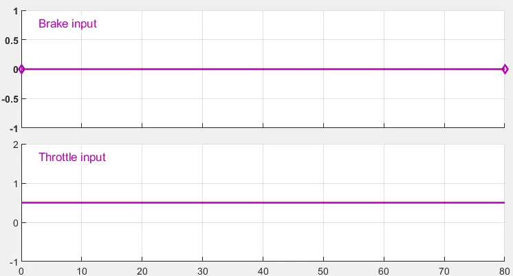
Throttle is at 0.5 while brake is 0 here. Solver configuration and mechanical reference is connected to port B of the engine. Engine sensor is connected to the port F of the engine representing mechanical rotation of the engine crankshaft. Port P and FC represent engine power and fuel consumption and are not being used in this model. Output of engine goes to engine sensor subsystem. F is the input of subsystem and B is the output.
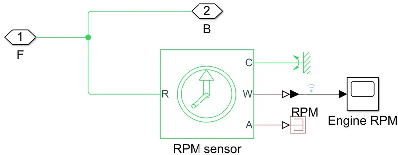
Input F directly goes to the output B which is the input for the simple gear. RPM sensor reads the input and angular velocity is displayed.
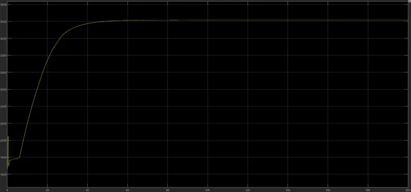
As we can see here engine RPM increases with time till 40 seconds and then remains constant till 200 seconds at 3400. Initial RPM is 1800 which spikes to 2000 before going down and coming back to 1800.
Output of cvtratio signal builder block & engine RPM sensor is fed to CVT subsystem. CVT is Continuous Variable Transmission which makes use of pulleys, belt and variator to increase or decrease speed.
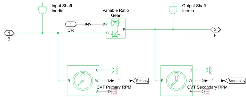
Variable Ratio Gear allows to set the gear ratio for primary and secondary shaft. Ratio input is being given at port 1(CR).
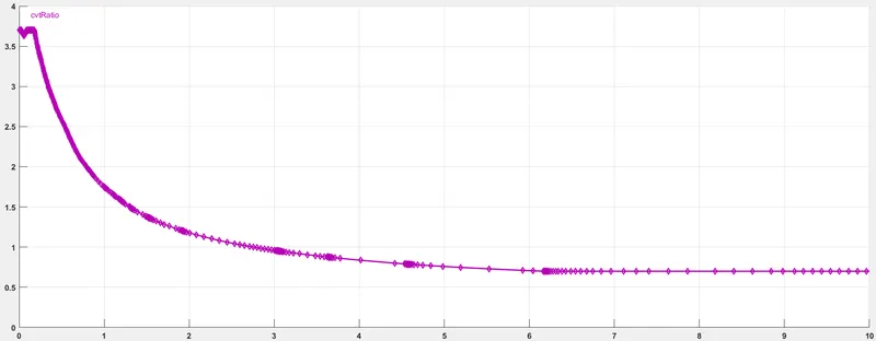
Initial ratio is a little more than 3.5 and then it gradually decreases to 0.75 which will lead to overdrive as the ratio is less than 1.
Input and output shaft inertia are primary and secondary pulley. Input Shaft Inertia is connected to port B, which represents base mechanical conserving port while Output Shaft Inertia is connected to port F representing follower mechanical rotational conserving port. Ideal Rotational Motion Sensors are connected to both the shafts to get angular velocity. Output of this subsystem is represented by port F which is the output of Variable Ratio Gear and represents mechanical rotational port.
The output of CVT goes to the gear which is set at 10:1 Follower to Base Teeth Ratio.
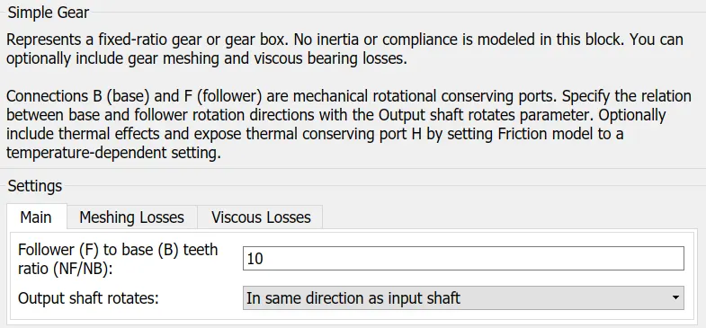
The speed decreases ten times due to this gear as follower gear rotates only 1 time if base gear rotates 10 times.
The gear output goes to vehicle body subsystem, which is composed of brake, tires and vehicle body block.
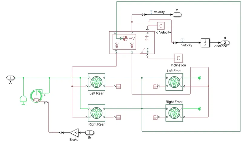
Brake input is applied from the first block of brake & throttle input. Default value of brake is 0 as no brake is applied. Its port is 1(Br). Gain of 1000 is applied to it. This signal goes to Double Shoe Brake block which works on Left Rear and Right Rear tires. A vehicle body block is included which is used to specify the parameters of the vehicle like mass, number of wheels per axle, drag, pitch and initial velocity. Vehicle body block has ports H, V, W, beta, NR and NF. H represents horizontal motion and is connected to the tires. V represents the vehicle velocity and is the output of this subsystem indicated by port 1(v). An integrator is also connected to V(velocity) port to get distance and the output is obtained at port 2(d). NF and NR represent front and rear normal wheel forces and are connected to N port of the front and rear tires. W represents the headwind speed and is connected to a constant block with 0 value. Beta represents road inclination angle and is connected to a constant block with 0 value.
The outputs are shown using display block. From block is used to get display input.
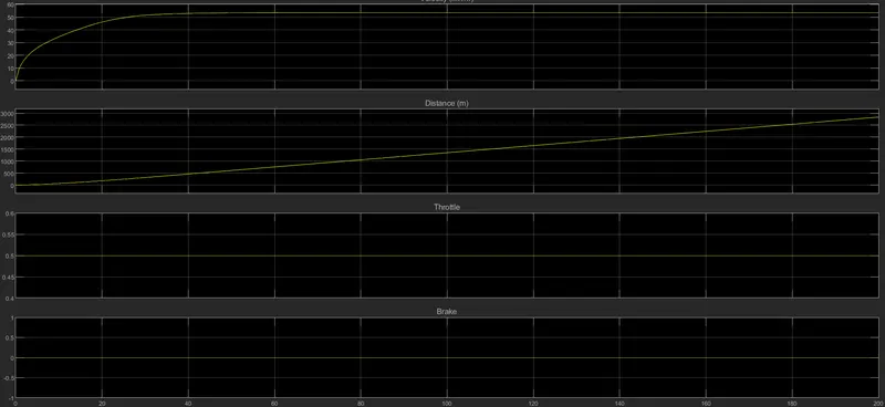
First display shows car velocity, distance travelled, engine throttle and brake. Car velocity increases from 0 to a bit more than 50 km/hr. in 40 seconds and stays constant here till the running time of 200 seconds. Distance travelled increases lightly in the beginning and then shows a linear increase till the end and reaches up to 3000m. Throttle is constant at 0.5 while brake is at 0.
The other display block shows primary and secondary shaft speed. Primary CVT RPM initial value is 2000 and increases to little more than 3000. CVT Secondary RPM initially is at 0 and rises to little less than 5000 in 40 seconds and stays nearly the same till the end. RPM increases as it is an overdrive. Engine-Torque speed curve has also been plotted.
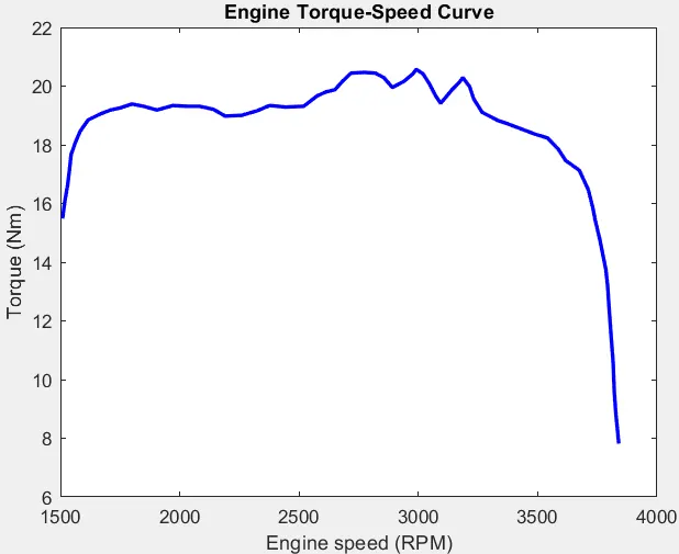
Torque initially is at 16Nm at 1500RPM and increases to 20Nm at 3000RPM and decreases to 8Nm at 3900RPM.
The second model of BAJA SAE is quite similar to the first one except that it has a dashboard with speedometer, RPM indicator, brake & throttle input to vary their values while the simulation is running.
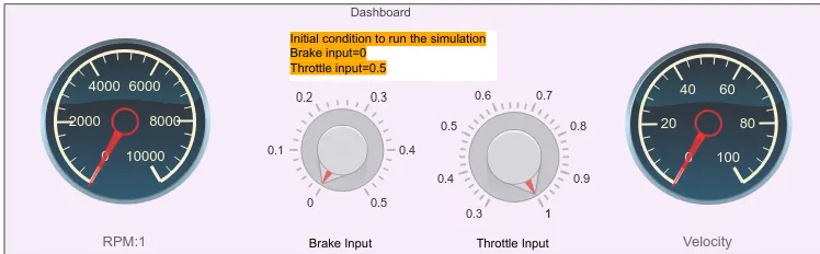
Velocity & RPM varies as the brake & throttle input is changed.
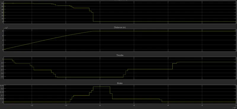
As the throttle is decreased, velocity also decreases and likewise if it is increases, velocity increases. When brake is applied, velocity comes down to 0. Distance travelled increases with velocity and vice versa.
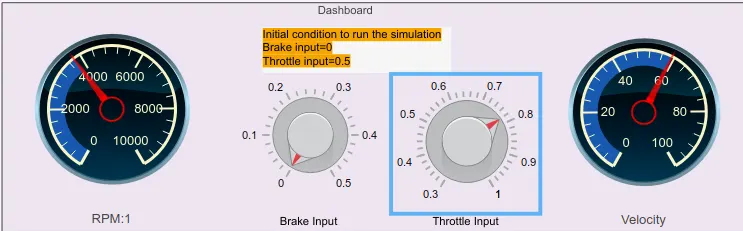
As we can see, velocity and RPM varies with change in throttle input.
Overall, this is a very informative model of ATV and helped in understanding its parameters and working.