Week - 4
Aim :
- Implement control logic of a “washing machine” using Stateflow
- Make a Simulink chart for the “Gear shift”
Objective :
-
- Implement control logic of a “washing machine” using Stateflow as per given sequence:
- If the power supply is available, the system gets activated
- If the Water supply is not available, stop the process & indicate through LED
- Soaking time should be 200s followed by Washing time of 100s.
- Then rinsing happens for next 20s & dryer runs for 50s
After all the processes have completed turn on the finished LED
-
Make a Simulink chart for the “Gear shift” logic as per below conditions:
Speed Range(kmph) Gear
0 to 15 1
16 to 25 2
26 to 40 3
41 to 60 4
Above 61 5
Give speed input while the simulation is running & display the gear number.
stateflow :
Control the behavior of a Stateflow chart by using actions in states and transitions. Design logic at multiple levels in a complex system by using hierarchy. Implement operating modes that are active at the same time by using parallel states. Broadcast events from one state to another to synchronize parallel states.
#first
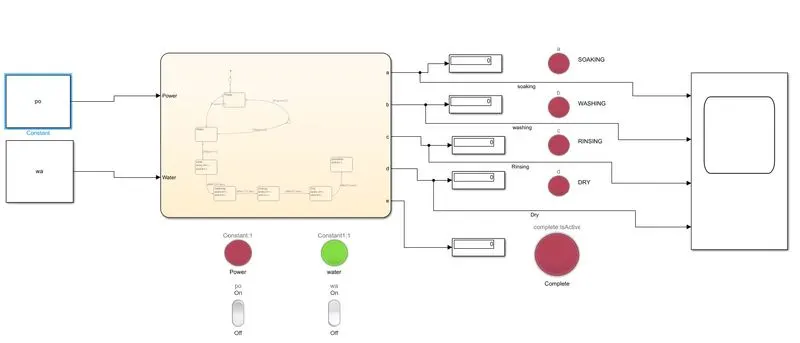
simulink chart model for washing mashine control logic
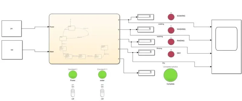
Explaination of model :
- chart block
- lamp
- constant
- Rocker switch
- Display
in the chart block our main logic is created
constant block are used to input the power and water input
rocker switch is used to indicate the ON and OFF of the power and water supply.
lamp is used to indicate the which process is going on
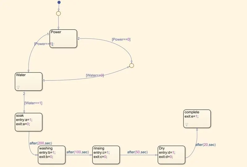
Here in the above chart all the state are assigned and there action.water,soak,washing,rinsing,dry,complete and power are the state and named according to there work.This state comes in action according to the condition.
like soaking process will be start only when water and power supply is equal to 1 that mean when water and power supply is there.
Output when power and water supply is ON :
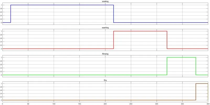
- above result shows the duration of the processes.
Ouptput when power supply is ON but water supply is OFF
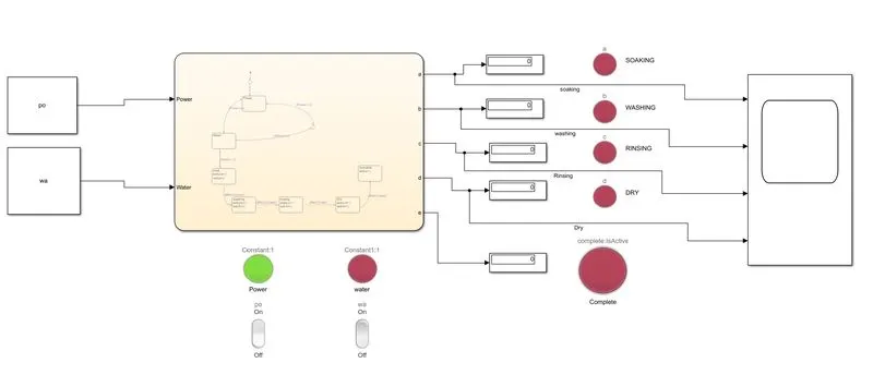
- due water supply is not there all the next processes get stopped shows red sign
Output when water supply is ON but power supply is OFF
- due to power supply is off all the next processes get stopped
- to complete all the processes power and water supply should be on
#second
simulink chart model for gear shift
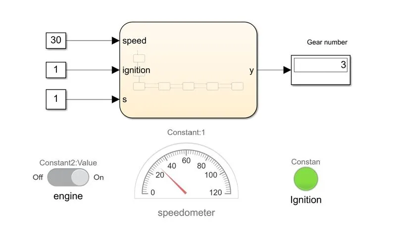
Explaination of model :
- chart block
- lamp
- constant
- half gauge
- display block
- switch dashboard
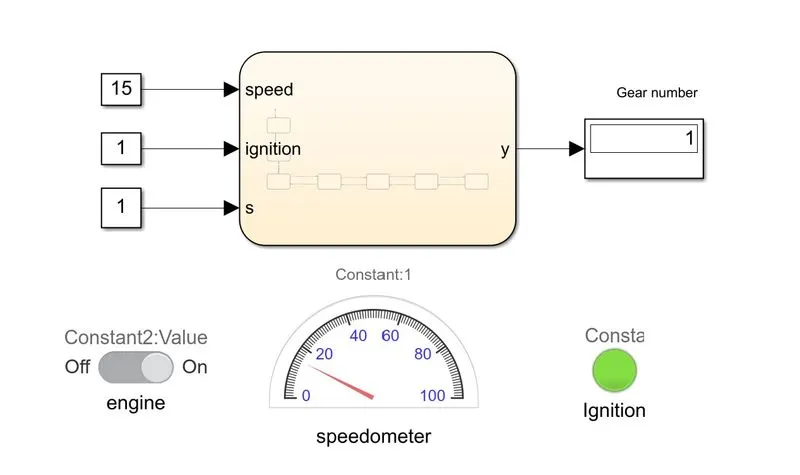
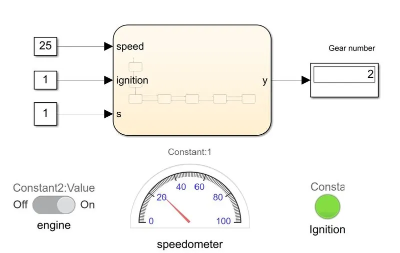
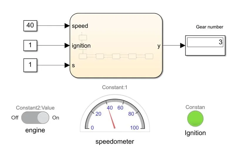
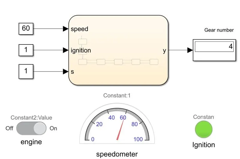
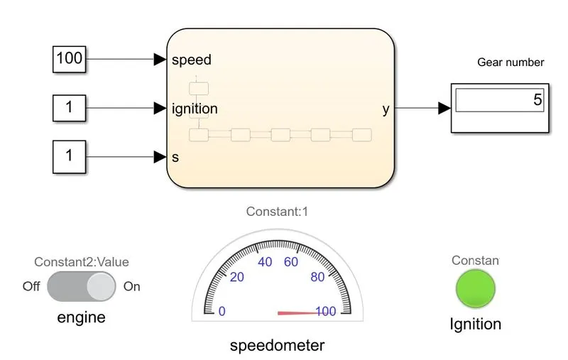
constant block are used as input for speed , s , ignition
all the logical controlled in chart block
switch is used to on and off the engine which connected to the s parameter
speedometer connected to speed data
y is an output which shows the gear number using display block
lamp shows the ON and OFF of the engine.
stateflow chart for gear shift
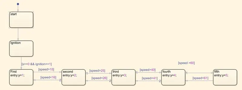
Stateflow chart used the get the logic of automatic gear shifting processes.
start,ignition,first,second...fifth are the state.These state and there action get executed according to there speed condition
like speed >15 which is our condition to go second gear,if speed is 14 then gear should be the first one.
Output when engine is turn off :ie no ignition
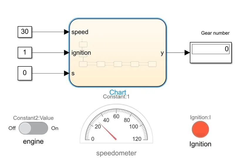
- Because of the engine is off there will be no ignition showed by red lamp sign and also no gear shift
Output when engine is turned ON and speed is 15 :
Output when engine is turned ON and speed is 25 :
Output when engine is turned ON and speed is 40 :
Output when engine is turned ON and speed is 60 :
Output when engine is turned ON and speed is 100 :
Conclusion :
- This is how we can simulate the control logic of washing machine and gear shift using the stateflow chart.