Week 4.2: Project - Transient simulation of flow over a throttle body
I. INTRODUCTION
A throttle is a mechanism by which fluid flow is managed by constriction or obstruction. An engine's power can be increased or decreased by the restriction of inlet gases (by the use of a throttle), but usually decreased. The term throttle has come to refer, informally, to any mechanism by which the power or speed of an engine is regulated, such as a car's accelerator pedal.
II. OBJECTIVE
1. Simulate fluid flow over a throttle body using a transient state solver.
2. Plot and analyze Velocity and Pressure Contours
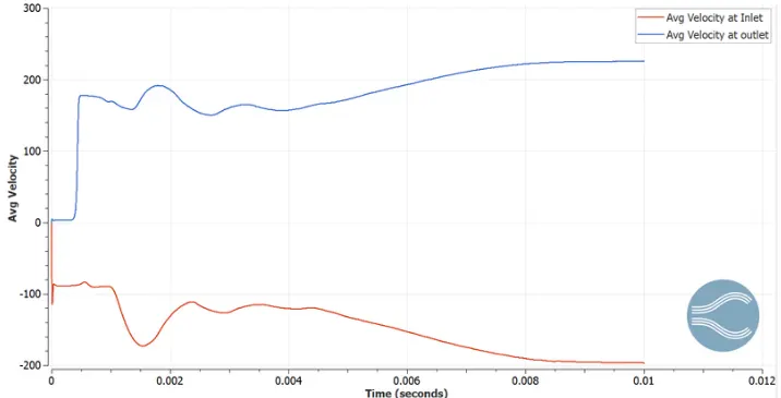
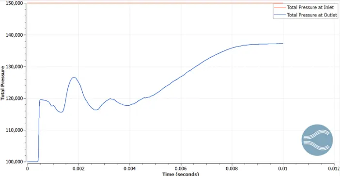
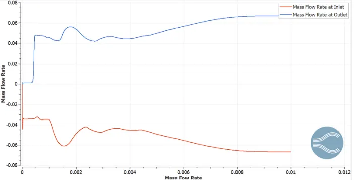
3. Plot and analyze Velocity, Pressure, Mass flow rate, total cell count.
III. GEOMETRY
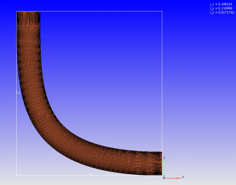
The geometry consists of 4 basic components:
Elbow Wall
• Inlet
• Outlet
• Throttle
Geometry setup
Case setup
1. Fluid :Air
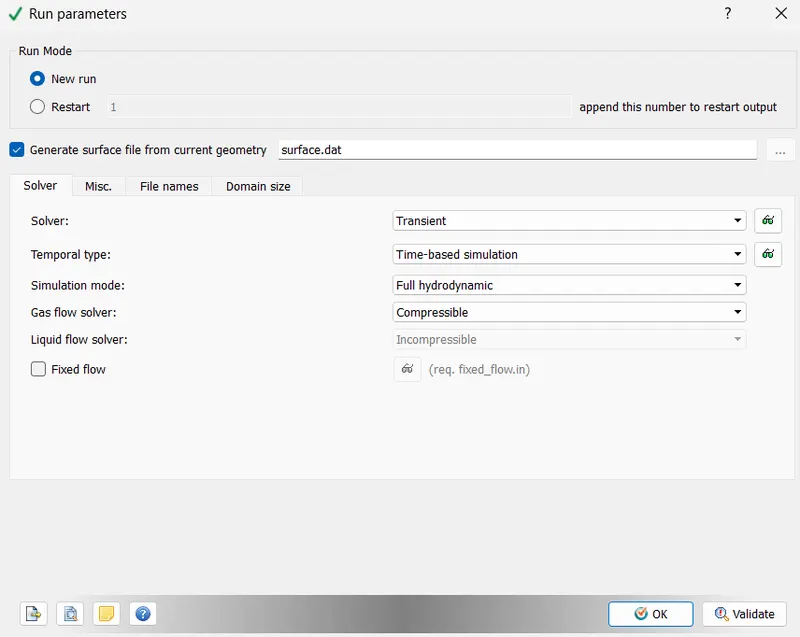
2. Run Parameter
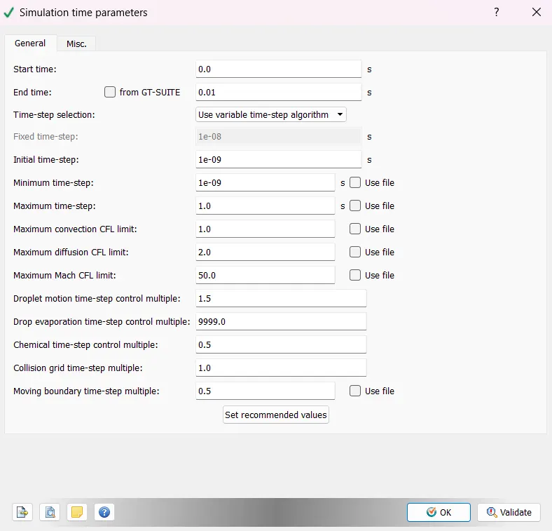
3. Simulation time parameter
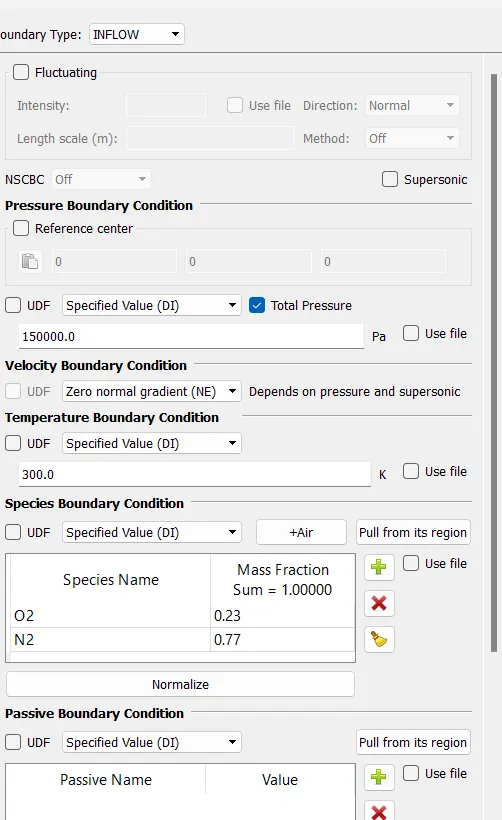
4. Boundary
inlet
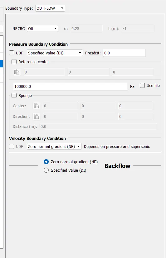
outlet
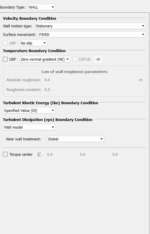
elbow wall
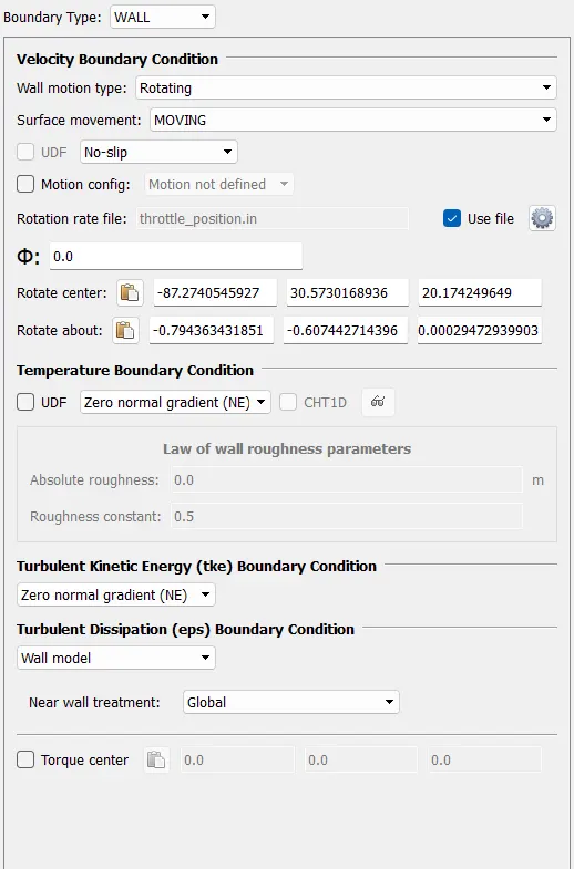
Throttle
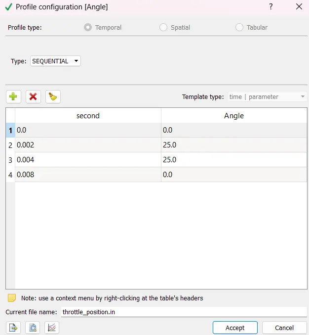
rotation rate file
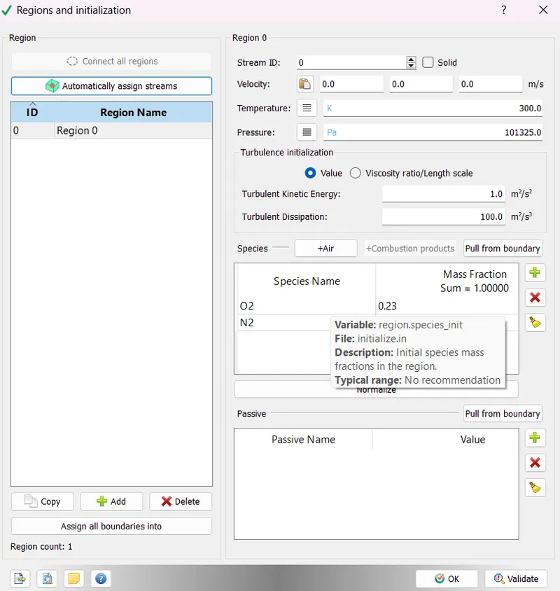
5. Regions and initialisation
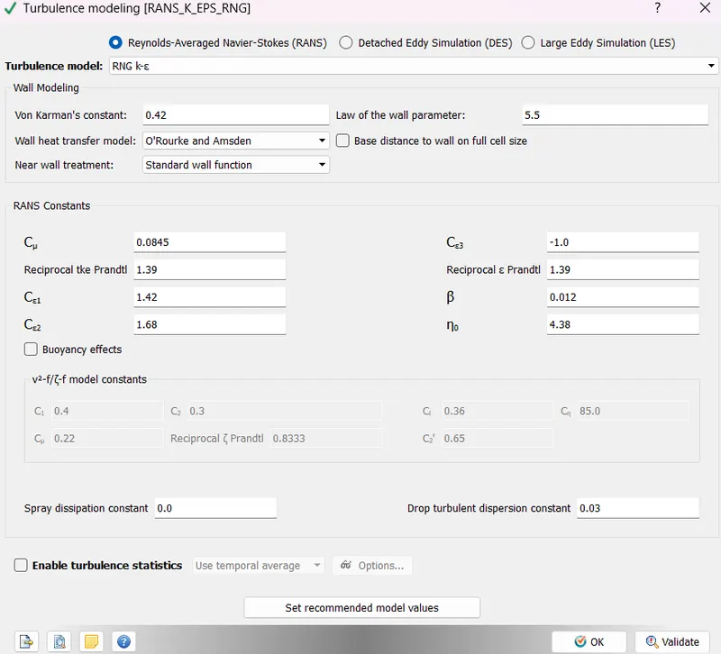
6. Turbulence Model
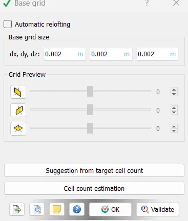
7. Grid control
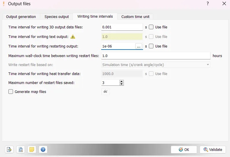
8. output files
Results
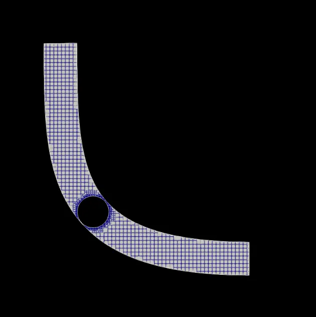
1. mesh
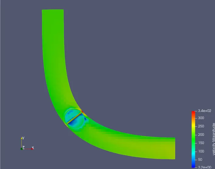
2. velocity contour
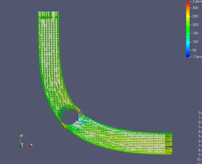
velocity vector
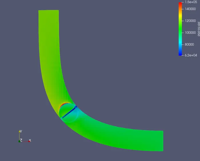
3. pressure contour
4. Variation of average velocity
5 Variation of pressure
6. Variation of mass flow rate
conclusion
Analyzing the behavior of the fluid helps us to understand and control the flow and the throttle movement such that we get the required output without any disturbances or irregularities. This helps to control the flow behavior and output depending on the requirement or application of the model.