Week 4.2: Project - Transient simulation of flow over a throttle body
OBJECTIVE: To simulate steady-state flow over a throttle body.
THEORY: In a conventional gasoline engine, a throttle valve is used in the intake manifold to reduce the power output for part-load operation. Varying the throttle position controls the amount of air-fuel mixture inside the engine, while the AFR is kept constant. A throttle is a mechanism by which the fluid flow is managed by construction or obstruction.A disc is mounted on a rod connected with an actuator, when the valve is closed the disc turns so that it completely blocks the fluid flow passage. They are prefered due to their cost effectiveness and easy maintainability.
SIMULATION PROCEDURE: We start of by importing the geometry in converge after which we remove the external surface, as theere is no need for it coz we are only interested in fluid flow volume and effect of valve position on the flow. Ince we cleanup our surfaces and do the required patching of inlet and outlet points we run a diagnosis test to verify the sufrace clean up and rectify any left out error in the surface as it may lead to simulation errors.
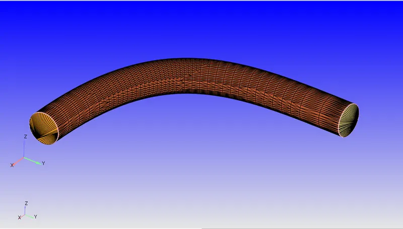
After cleaning and setting up our model we head towards boundary flaging where we manily flag our model into 4 different boundaries named inlet, outlet, throttle body, and throttle valve. Once our boundaries are flagged we head to setup our case, which we do by clicking begin case setup in which we select 'time based simulation' and our time based simulation tree is created which we setup step by step as per our requirements for the solution.
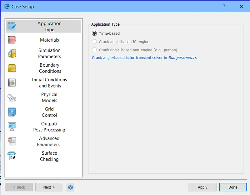
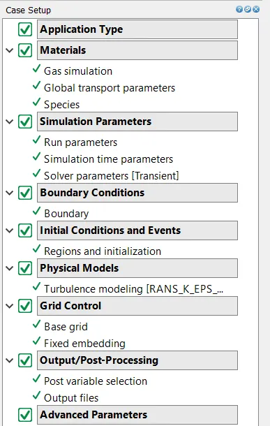
In materials reaction mechanism is unchecked as there is no reaction happening and species is enabled. All the sub-parameters in the setup tree are validated at their default values. And we head to simulation parameters.
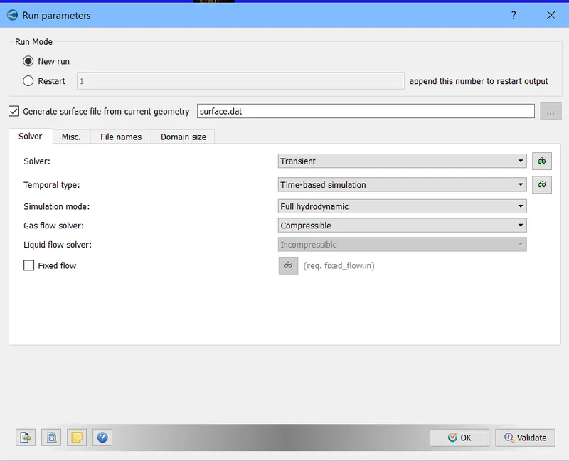
where we fisrt setup our run parameter where transient solver is selected and solver method is full hydrodynamic case.
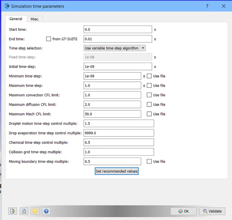
After this we setup our simulation time parameters where minimum time step is set to be 1e-9 and the maximum is 1 and simulation end time is 0.01 which we achieved by estimating the distance fluid travels in the tube and then dividing it by the average velocity in the steady state case and mulitpying the achieved time by 4 so that we can have 4 different fluid positions complete the run in the tube.
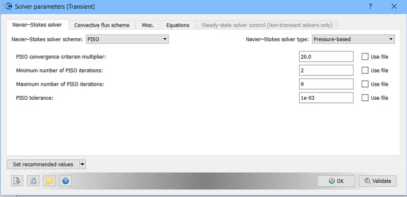
After this solver parameters were setup
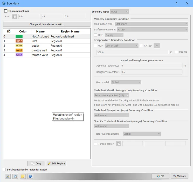
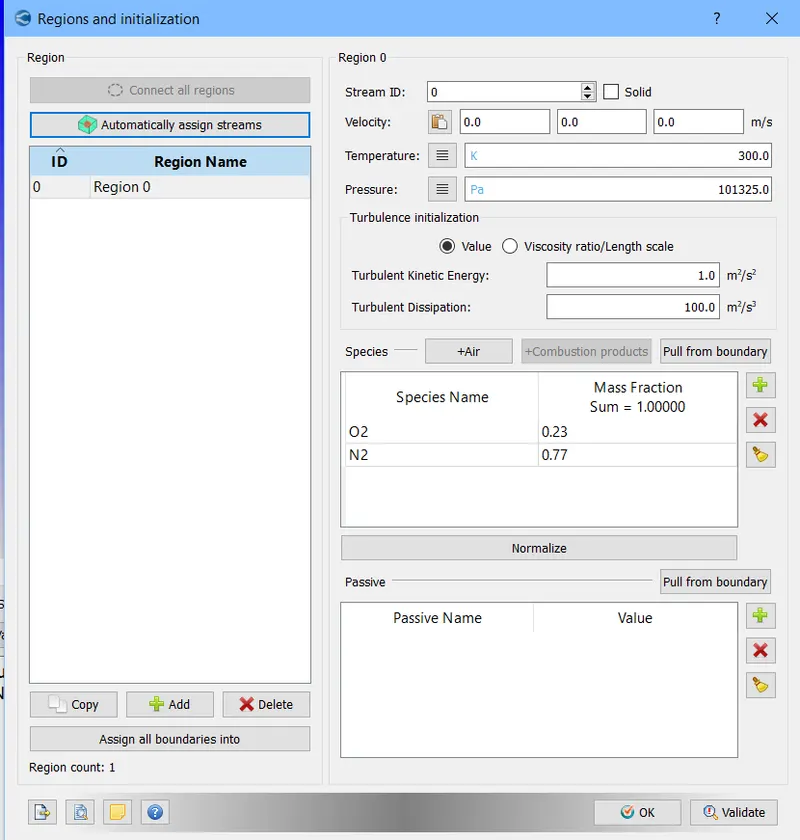
And after this we setup our boundaries and regions and provide the details same as in the steady state case-setup.
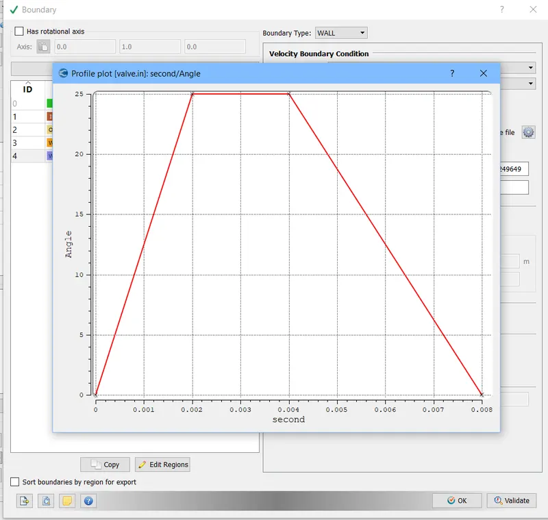
Here throttle valve was setup as moving boundary and the conditions of movement were given same as that asked.
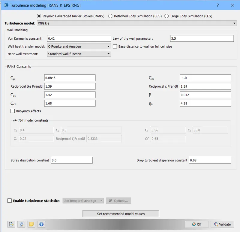
After this for the turbulence model RNG K-epsilon was selected
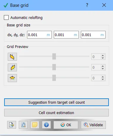
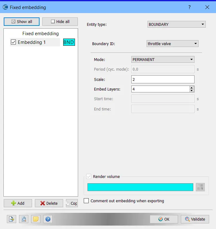
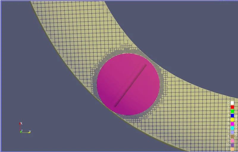
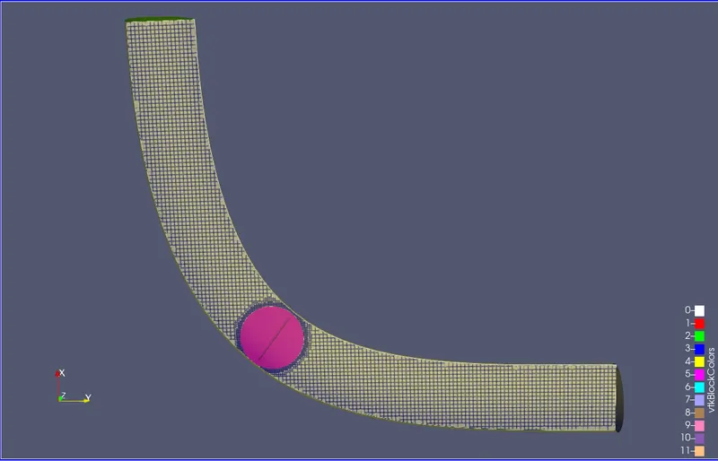
Base mesh size was set to be 0.001m and the fixed embedding was applied for throttle valve.
RESULTS:
GENERATED MESH
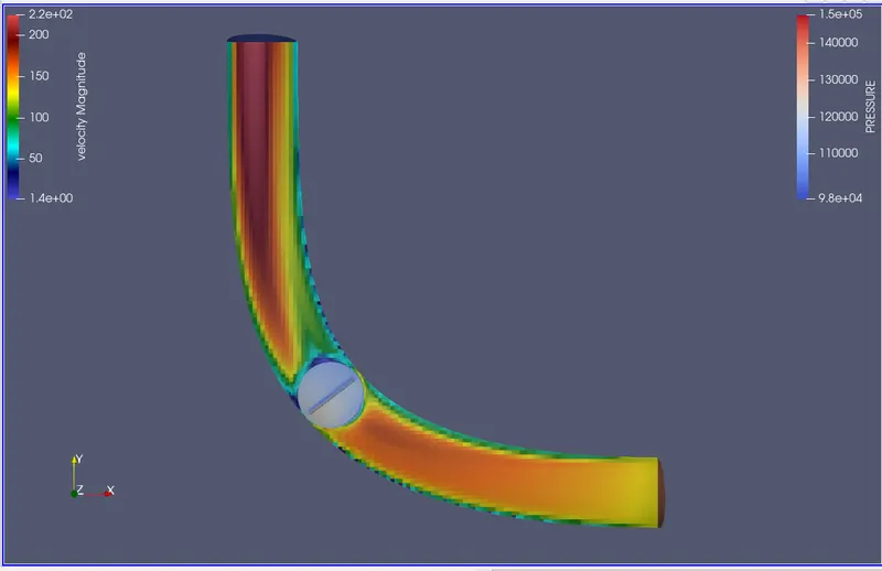
VELOCITY CONTOUR
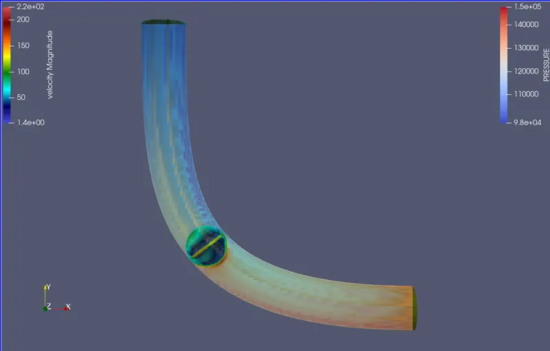
PRESSURE CONTOUR
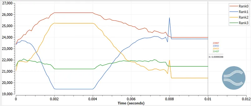
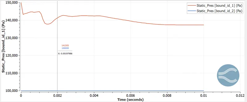
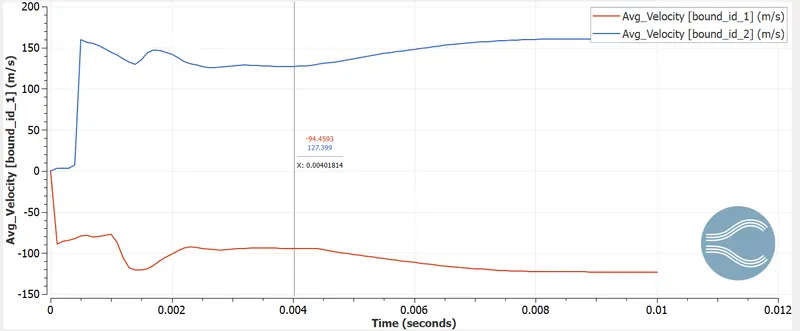
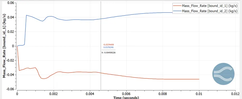
GRAPHICAL PLOTS OF VARIOUS PROPERTIES
CONCLUSION:
We can observe number of cells changing due to the movement in throttle valve.
We observe as the valve moves it causes restriction to fluid flow increasing the pressure in the region of valve. As the valve moves and restricts the flow velocity at the edges of the valve seems to increase due to pressure variations. Similar trend is observed in the pressure contour.