Week 4.2: Project - Transient simulation of flow over a throttle body
Aim:
Setup and run transient state simulation for flow over a throttle body.
Objective:
Post process the results and show pressure and velocity contours.
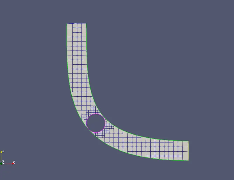
Show the mesh (i.e surface with edges)
Show the plots for pressure, velocity, mass flow rate and total cell count.
Also show the calculations on how you calculated an end time for the simulation.
Create an animation in which it throttle movement should be visible.
- Upload an animation on You tube and provide the You tube link for an animation in your report.
Theory:
In this Transient Simulation, the throttle is rotating and that we have an interest to simulate the flow at a special gap angle of the throttle.
The main operate of a throttle body assembly is to manage the air flow into the engine supported vehicle demand. The throttle body is mounted between the air filter and therefore the manifold. Following the angle of the accelerator (butterfly valve) changes, it restricts the number of air flow into the engine cylinder.
It has a venturi to scale back the pressure of the air flowing through it. The intake flow is throttled by reducing the flow space. this can be done by providing a circular shaft referred to as throttle shaft and is mounted with a valve at the downstream of the venture. the most challenge is that the modification in throttle position throughout transient operation of the engine, that introduces extra issues because the butterfly position is often modified as per driver’s demand. The air flow may be thought-about as unaffected by the fuel flow. However, the reverse isn't true and fuel flow powerfully depends upon the air flow. The schematic of a throttle body assembly describing the air flow path is shown in Fig one. Filtered air enters into the throttle body and moves downstream. valve (or throttle valve), restricts the number of air flow into the engine supported the accelerator position. There exists a bypass passage (Fig. 2), that is employed for adjusting the air flow at idleness conditions.
Model:
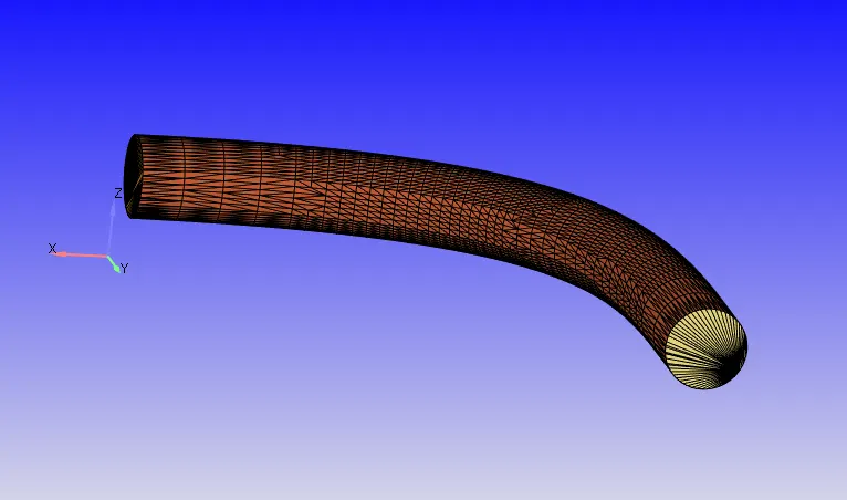
Boundary conditions
In this study, 3 styles of boundaries square measure concerned, viz., inlet, outlet and wall. water pressure boundary conditions square measure accustomed outline the fluid pressure at the flow water. Pressure water boundary conditions square measure used once the water pressure is understood, however the rate of flow or speed isn't famed. Outlet pressure boundary conditions need the specification of static pressure at the outlet boundary.
Simulation:
The following Simulation tools are incorporated:
1. Converge studio:- To pre-process the information that must simulate the case. It plays vital|a crucial|a vital|a very important} role in generating important 3d input files solely exploitation graphical user interface. It doesn't run simulation directly, but it generates inputs files that use to run the simulation.
Cygwin:- Cygwin may be a assortment of antelope and ASCII text file tools that offer practicality just like UNIX operating system distribution on windows.
Converge msmpi three.0:- To run the simulation exploitation these input files in Cygwin nonparallel or in parallel.
Post convert:- To convert all the output files that square measure processed by converge msmpi into the files which can be decipherable for post-processing in Paraview.
Paraview:- To post-processing to get the contour, plots, etc. it's associate degree ASCII text file, multi-platform knowledge analysis and image software system.
Geometry Setup:
Import the “stl” file.
Create associate degree automatic Boundary fence. Boundary->Find/clean->Find.
Delete the outer thickness of the Elbow by “by Angle” possibility.
Patch the Open edges by Patch tool. choose Patch(under Repair)-> “By open edges”-> choose water edges -> enter. Same for outlet.
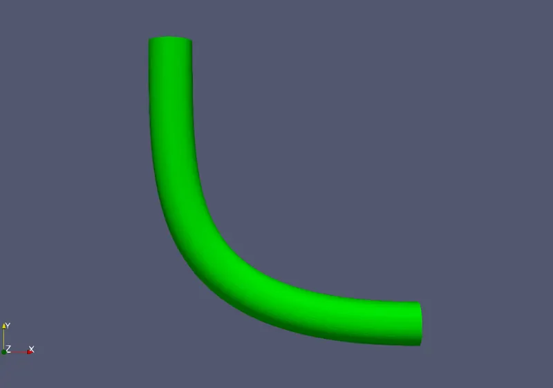
Boundary tired
Case Setup/Simulation Setup:
MATERIAL:
Gas Simulation:
As solely air is our operating medium therefore uncheck Reaction Mechanism.
Predefined mixture: air
Global Transport Properties
Turbulent Prandtl number: zero.9
Turbulent Schmidt number: zero.78
SIMULATION PARAMETER:
Run Parameter:
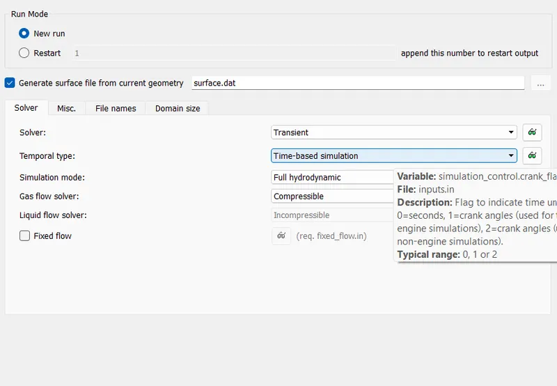
Solver: Pressure-based Transient problem solver.
Simulation Mode: No hydraulics
Gas flow Solver: Compressible (as air is functioning medium)
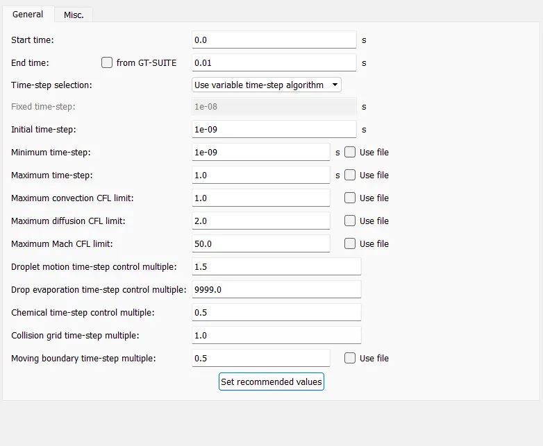
Simulation Time Parameter:
End time: zero.01 second
Start time: 0sec
Initial time step: 1e-06 s
Minimum time step: 1e-06 s
Maximum time step: one s
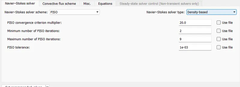
Solver Type:
Pressure primarily based
BOUNDARY:
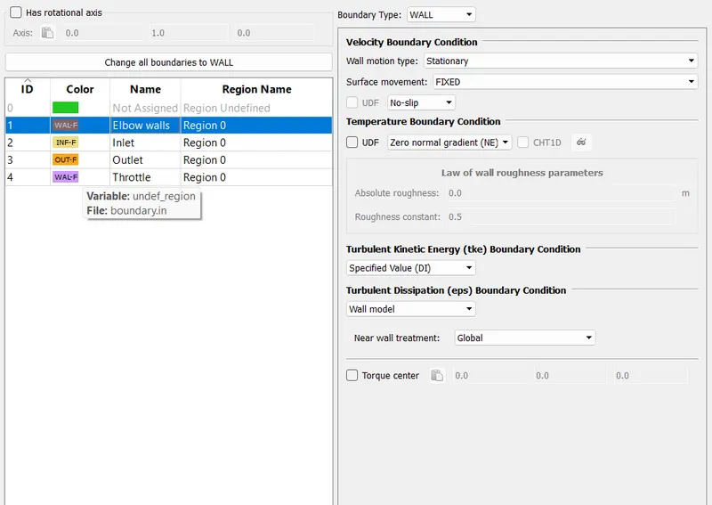
Naming: choose faces and name as water, outlet, Elbow wall, Throttle.
Boundary condition:
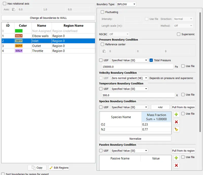
Inlet:
Boundary Type: flow
Total Pressure: one.5e5 Pa
Specified Boundary condition: alter Total Pressure
Species Boundary condition: air
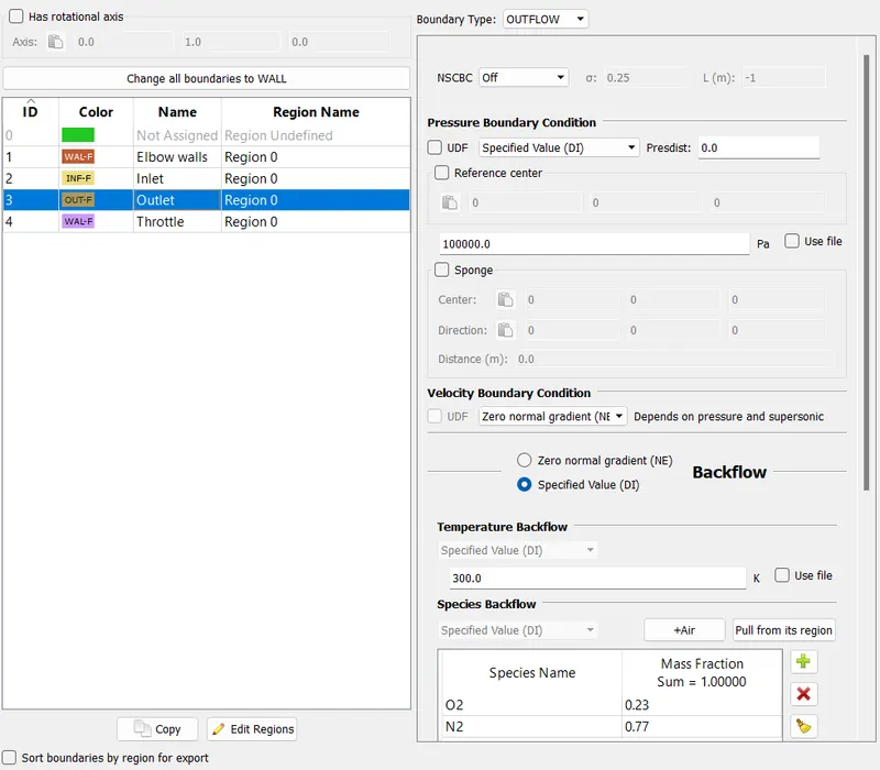
Outlet:
Boundary type: OUTFLOW
Static Pressure: 1e5 Pa
Convert law of wall into no-slip for top-bottom-wall below speed stipulation.
Elbow wall:
Boundary type: Wall
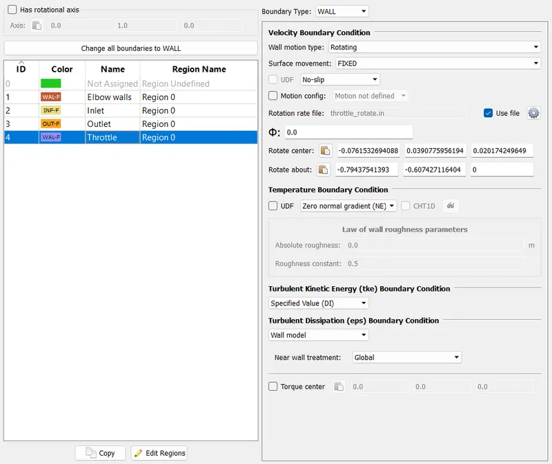
Throttle:
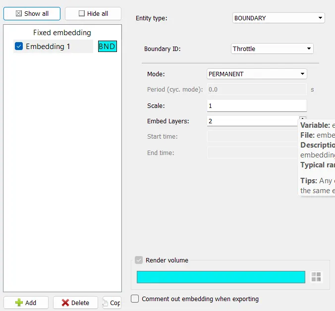
Boundary type: wall
Wall motion type: Rotating
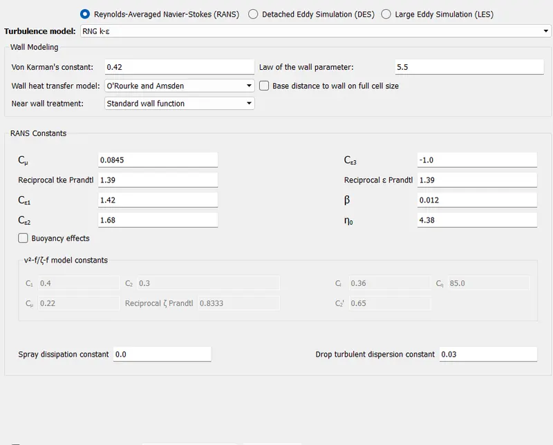
Velocity BT: Law of wall (as the flow is Turbulence)
Temperature BT: Law of wall.
REGION & INITIALIZATION:
Click on Region and initialisation
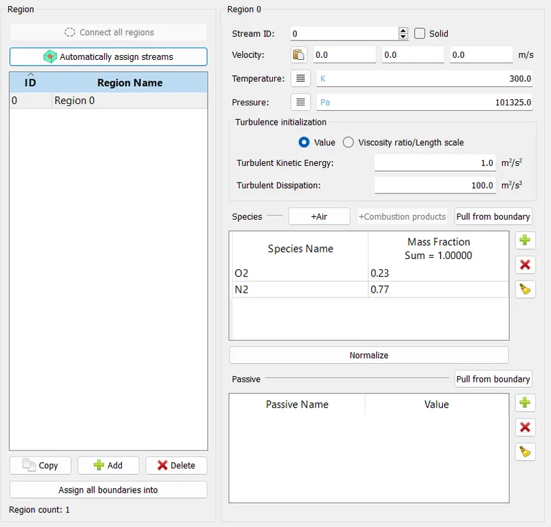
Add species: +air
O2=0.77 & N2=0.3
Base grid:
dx=0.002m; dy=0.002m; dz=0.002m
Post-variable selection:
Output files:
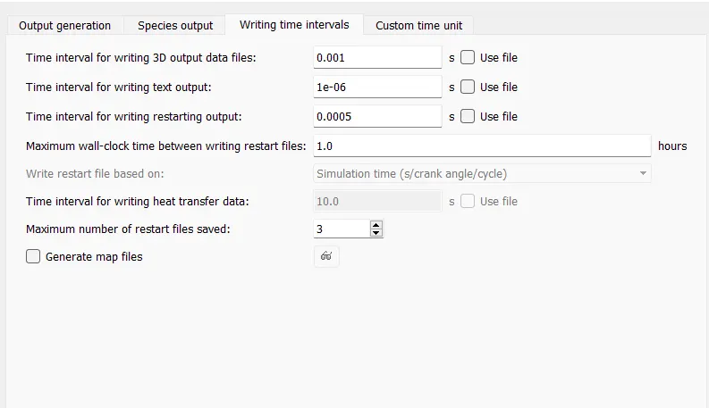
The quantity for writing 3d output knowledge files=40cyc
The quantity for writing restarting output=40cyc
Export input files and Running the Simulation:
Now we've with success got wind of the Case and wish to export the input files to run the Simulation.
Run the Simulation in Cygwin employing a parallel processor.
Post Converting:
Now we'd like to convert all the output files that square measure processed by converge msmpi into the files which can be decipherable for post-processing in Paraview
Paraview:
We need to Post-process the output files to get the contour.
The velocity is most at the aspect of the throttle because of creation of venturi(low space region) and there's negative pressure behind the throttle because of unforeseen breaking of flow.
Behind the throttle, the speed is minimum as a result of there's a flow separation, going away vacuum or nonaggressive area within which air isn't able to fill properly. This results in the formation of vortices because of dynamic of rate gradient from positive into a negative price at this time. therefore this time is named some extent of separation. during this purpose of Separation, the speed profile du/dy is zero at the wall. If the adverse pressure gradient acts over a sufficiently extended distance, the speed within the flow are adequate to alter the direction of the flow within the physical phenomenon. therefore the physical phenomenon develops the purpose of Inflection, called the purpose of physical phenomenon Separation on the far side that a circular flow pattern is established.
Conclusion:
As the Mass flow and speed increase apace for the time of 0-2 msec for the Valve angle of twenty five degrees whereas the pressure reduces apace. this is often thanks to the sudden decrease within the space that acts as a venturi or as a nozzle. more will increase in time from 2-4 milliseconds, the valve is idle. And for 4-8 msec, the valve regains its original position that creates will increase within the space thence pressure reduces step by step, and speed and mass flow increase step by step. when 8milliseconds, the mass flow, pressure, and speed is constant.
The cell counts fluctuate thanks to the movement of the throttle. it's conjointly referred to as because the Dynamic meshing. For 0-2 ms, the world is reducing, thus cell counts have to be compelled to will increase and mesh needs to become finer to capture the physics accurately at the minimum region. For 2-4 ms the valve is idle thence the cell counts aren't dynamic more reducing the world from 4-8 ms, the cell counts have to be compelled to decrease. when 8ms the throttle position is constant thence no changes in cell counts.
Behind the throttle, the rate is minimum as a result of there's a flow separation, going away vacuum or unaggressive house within which air isn't able to fill properly. This results in the formation of vortices thanks to dynamic of speed gradient from positive into a negative worth at this time. thence this time is termed a degree of separation. during this purpose of Separation, the rate profile du/dy is zero at the wall. If the adverse pressure gradient acts over a sufficiently extended distance, the fastness within the flow are ample to alter the direction of the flow within the physical phenomenon. thence the physical phenomenon develops the purpose of Inflection, referred to as the purpose of physical phenomenon Separation on the far side that a circular flow pattern is established.