Week 4-1D Element Creation Challenge
OBEJECTIVE:
To mesh the given compents in 1D elements and give DOF and cross section to them.
MODEL:
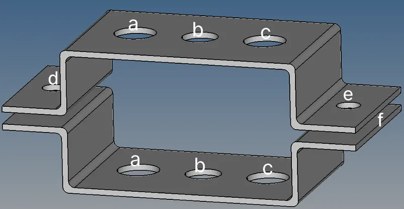
Procedure:
- First import the model from the saved area
- Now we have a model in soild cross section but we are here doing a 1D mesh so for that we are creating an midsrface for every model For every midsurface we need to create an iduvidual compents so we can create a good midsurface .
- The model is given materials, properties and thickness as required induviduvally for every compents we give the material as steel and the thickness for bracket 1& 2 - 3.5 ,3 mm
- The soilds are removed and we have the midsurfaces alone now with this we are going to create a 2D mesh for the component
- Before creating the mesh we need to conform tht model will produces a good mesh for tht we are using washer spilt to improve the quality of the mesh .
- Now we select the compents and create mesh by clicking on the 2D > automesh > select the surface > mesh size 5 units > type of the mesh quads > mesh .
- We have the totally meshed two compents we addjust the no of nodes in the hole area to capture the dia properly and produce a good mesh around the hole area.
- As per the given diagram we make a
a. Rod element:- Translational DOF should be Constrained with RBE2 link
Cross-Section: BOX- Dimension a= 12 mm
dimension b=10 mm
Thickness t= 0.75 mm
b. Beam element:- All DOF should be constrained with RBE3 link
Cross-Section: I Section- Dimension a= 8 mm
Dimension b= 10 mm
Dimension c= 8.5 mm
Thickness t1= 0.75 mm
Thickness t2= .6 mm
Thickness t3= .6 mm
c. Bar element:- Constrain only x and y DOFs With RBE3 link
Cross-section: X section- Dimension DIM1= 5 mm
Thickness DIM2= 1.2 mm
Dimension DIM3= 10 mm
Thickness DIM4= 1.2mm
d. & e. Apply the mass of magnitude 10 with the RBE2 link
f. Join the two components with Spring elements .
- Now we start with the A by creating an RBE2 link for this we use 1D element >rigidts >calculate node >mutilpies node >nodes > by path > create now we have craeted in the bracket _1 follow the same for bracket _2 component .
- Then create a rod element in between by rod > select nodes a&b > create and we have a rod element .
- Do the same for b,c,d,e and f as per the question given and create links ,elements & mass over the compent.
- Now we should assign the cross section for the elements given in the component for that we use HYPERBEAM .
- Then assign the cross section to the given links in a,b and c by clicking on the Bar > cross section > select the bar , repeat this for remaining cross sections to the compents .
- Assign mass on points d & e by > 1D > masses > select the node > enter the mass acting on the node > create . Now we have to do the same command for e point also .
- We need to place the spirng element point f >1D > spring > select the node A&B > create , then create the same spring element on the other side of the bracket .
Result:
The given compents is meshed with given rbe2 ,rbe3 links in the area required with the DOF's wanted and BAR, BEAM ,ROD and spring elements are created .