Week 4-1D Element Creation Challenge
Objective:
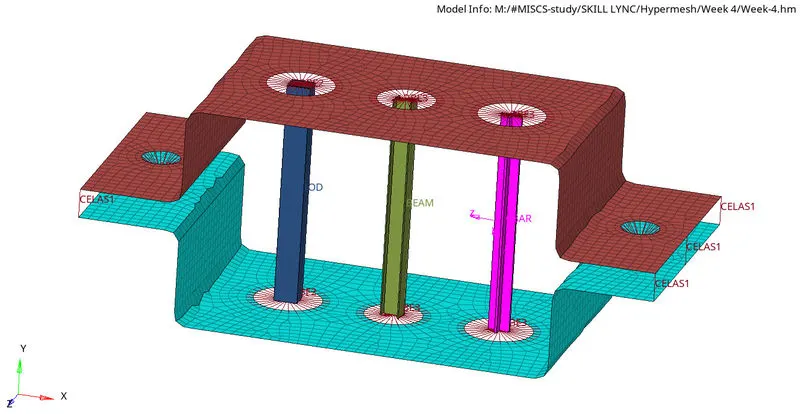
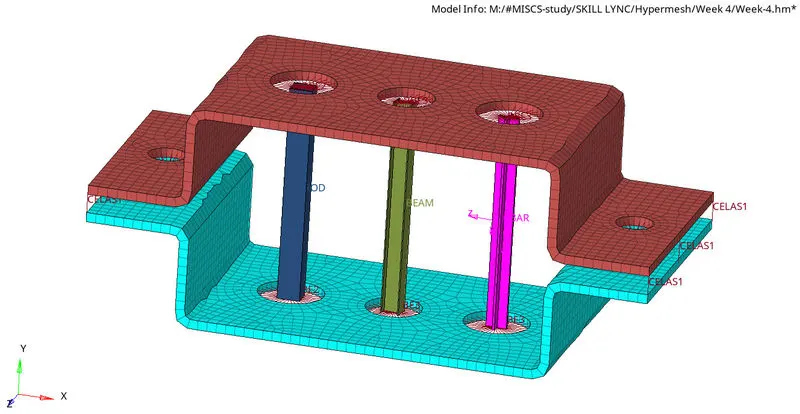
To mesh the given component with element size as 5 units and to create the following 1D components.
| A | B | C | D & E | F | |
| Element type | ROD | BEAM | BAR | MASS | SPRING |
| Cross-section | BOX | I-SHAPED | X-SHAPED | - | - |
| Dimensions | a=12, b=10 | a=8, b=10, c=8.5 | DIM1= 5, DIM3= 10 | Mag=10 | - |
| Thickness | t=0.75 | t1=0.75, t2=0.6, t3=0.6 | DIM2= 1.2, DIM4= 1.2 | - | - |
Procedure:
Import model:
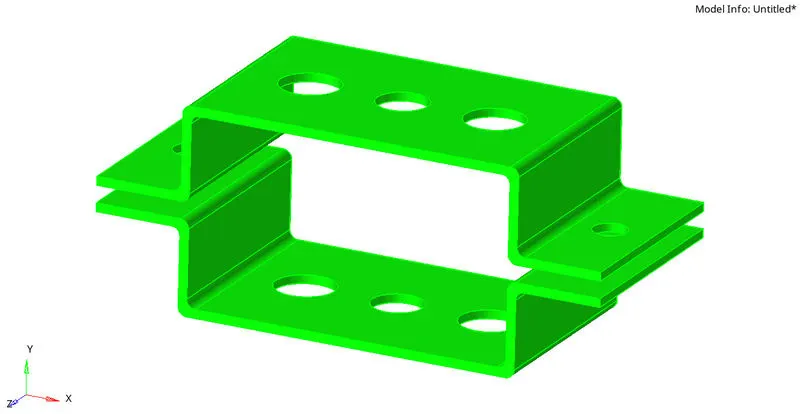
To import the cad model, goto New model > Import geometry and select the file to import.
Midsurface generation:
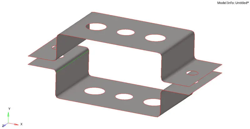
To create the midsurfaces for the brackets, goto Geometry > midsurface and select the solid to extract midsurface from and then click on extract.
Geometry cleanup:
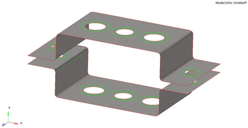
- To start with, goto Geometry > autocleanup and enter the target element size as 5 in the edit criteria & edit parameters menu.
- Select the surface to be cleaned up and click on autocleanup.
- The autocleanup function generates washers automatically.
Individual component creation:
- To assign the different surfaces to individual components, Right click on the Model browser and click on Create > Component.
- Then in the panel area goto Tool > Organize, select the surface and the respective component to which it has to be assigned and click on Move.
Property creation:
- To create a property, right click on the model browser and click on Create > Property. Choose the card image as PSHELL and enter the required thickness.
- To assign a particular property to a component, goto that component and click on property and select the desired property card.
Mesh generation:
- Next in order to mesh the surfaces, goto 2D > Automesh and enter the mesh element size = 5.
- Choose the surface to be meshed and click on the mesh button.

1D element cross-section Creation:
- To create the different cross-sections required, goto 1D > Hyper Beam > Standard section. Choose the Standard section library as HYPER BEAM for the I-section and BOX- sections and change the Standard section library to Optistruct for the X-section.
- Select the standard section type znd click on create, the HyperBeam view will open.
- Enter all the required dimensions for the section.
1D Elements Creation:
RBE2:
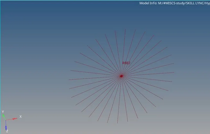
- To create a RBE2 element, goto 1D > rigids and select the nodes to which element has to be created.
- Select the dofs to be constrained and then click on create.
RBE3:
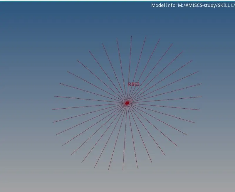
- To create a RBE3 element, goto 1D > RBE3 and select the nodes to which element has to be created.
- Select the dofs to be constrained and then click on create.
ROD:
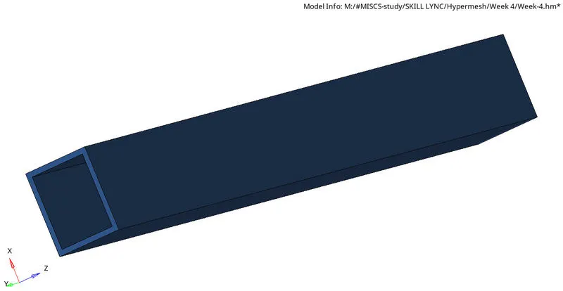
- Create a property named ROD with the card image as PROD. Choose the appropriate beam section.
- Goto 1D > rods, select the nodes and select the property. Change the element type to CROD.
BEAM:
- Create a property named BEAM with the card image as PBEAM. Choose the appropriate beam section.
- Goto 1D > bars, select the nodes and select the property. Change the element type to CBEAM.
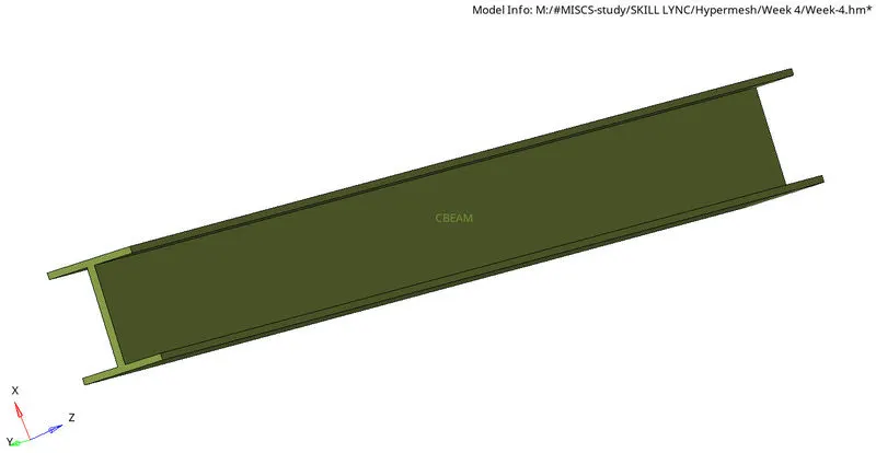
BAR:
- Create a property named BAR with the card image as PBAR. Choose the appropriate beam section.
- Goto 1D > bars, select the nodes and select the property. Change the element type to CBAR.
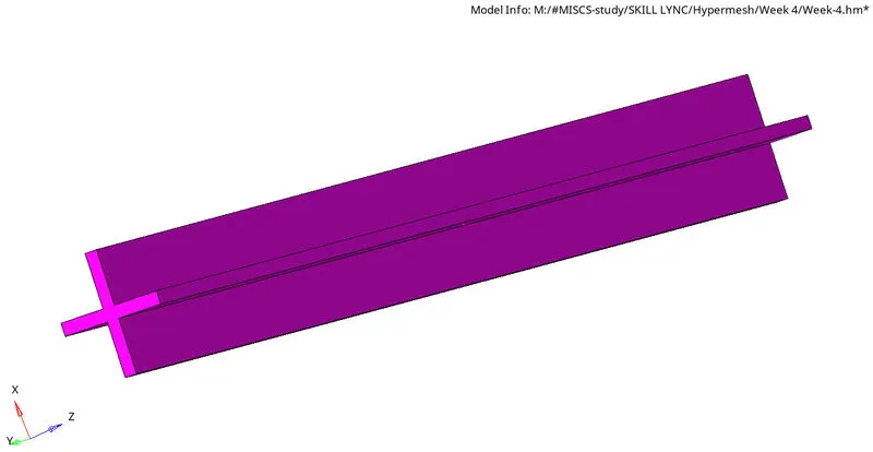
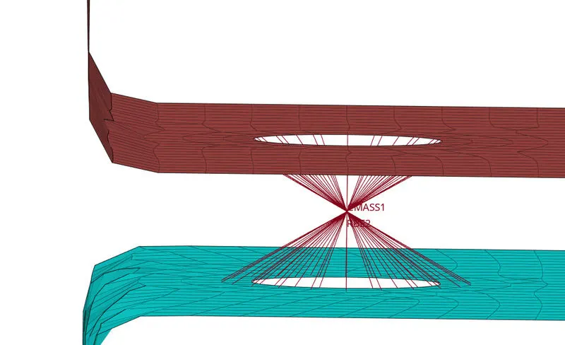
Mass:
- Goto 1D > Masses, select the node where the mass has to be applied and enter the magnitude of the mass.
- Choose element type as CMASS1 and then click on Create.
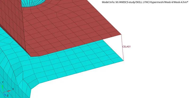
Spring:
- Create a property named Spring with the card image as PELAS.
- Goto 1D > Springs, select the nodes between which the spring element has to be created and select the property.
- Change the element type to CELAS.
NOTE:
- Enable 1D detailed Element representation to view all the elements' cross-sections.
- Enable 2D detailed Element representation to view all the elements' thickness.
Result:
Thus, the given component is meshed with element size = 5 units and the required 1D components were created.