Week 4-1D Element Creation Challenge
Challenge4:- To create 1D element on the given component.
OBJECTIVE:- To create 1D element such as ROD,BAR,BEAM on the given component and apply mass on the given component with given dimension and Degree of freedom(DOF).
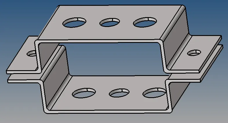
img1:create 1D element on the given component.
PROCEDURE:
- Import the STEP file by clicking FILE→IMPORT→GEOMETRY→PARALLEL BRACKET(FILE) and click Import.
- generate the Mid surface on the upper bracket:GEOMETRY→MID-SURFACE and select the upper part ,choose automesh option and click extract.
- Once the mid surface is extract on the upper bracket,name the midsurface on the tree as BRACKET_1 and select any colour for diffrentiate the upper bracket.
- Same thing is done for the lower bracket.
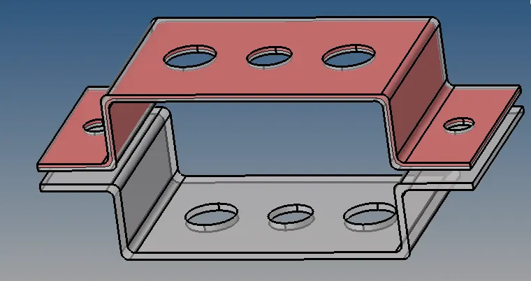
img2:midsuface extraction on the upper bracket
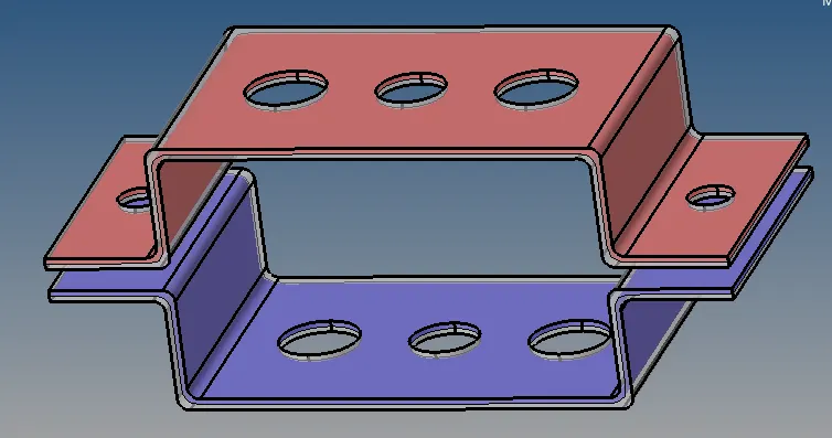
img3:midsurface extraction on the lower bracket
- Once the midsurface extraction is done, delete the solid part,
 .by clicking this icon and select the solid and click delete entity.And also delete the component in the model view.
 - Create component and move the lower bracket midsurface onto the component and name the component as BRACKET_2 delete the previous midsurface file,now we have two separate midsurface file.
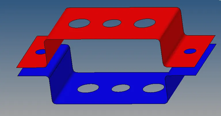
img4:deletion of the solid part
- After removal of solid part, give washer for every hole and create material,property for the given component.Give the material as MAT1 and assign the thickness in the property.
- click the each component and insert the property and the material.
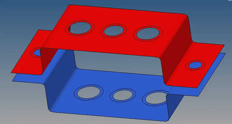
img:creating washer around the hole
- mesh the entire component with element size of 5mm with mixed type of element:2D→ Automesh →surf→ return
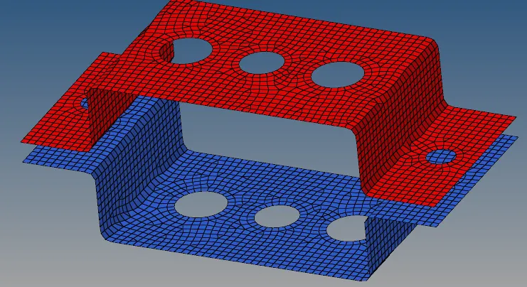
img:meshing of the entiure component.
- Next step is to create RBE2 and RBE3 elements.
- the diffrence between the RBE2 and RBE3 is that:
| RBE2 | RBE3 |
| The element have infinite stifness means it never bend and translate | The element can be moved |
| load distribution will be equal(uniform) | The load can be varied means it will not be uniform. |
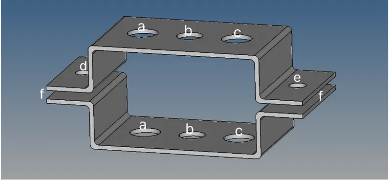
- The links and dimesion are given to the resperctive hole as per the problem statement.
-
a. Rod element:- Translational DOF should be Constrained with RBE2 link
Cross-Section: BOX- Dimension a= 12 mm
dimension b=10 mm
Thickness t= 0.75 mm
-
b. Beam element:- All DOF should be constrained with RBE3 link
Cross-Section: I Section- Dimension a= 8 mm
Dimension b= 10 mm
Dimension c= 8.5 mm
Thickness t1= 0.75 mm
Thickness t2= .6 mm
Thickness t3= .6 mm
-
c. Bar element:- Constrain only x and y DOFs With RBE3 link
Cross-section: X section- Dimension DIM1= 5 mm
Thickness DIM2= 1.2 mm
Dimension DIM3= 10 mm
Thickness DIM4= 1.2mm
- For create rod element go to the HYPERBEAM→STANDARD SECTION→THIN WALLED BOX→CREATE.
- give the dimesnion for the thin walled box as per the given statement.
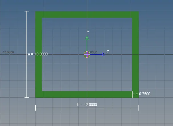
img:thin walled tube(rod)
- same like, create the remaining model BEAM and BAR,go to the hyperbeam view window click left mouse button and choose create→standard section→hypermesh→standard I section.And give the dimesnion.
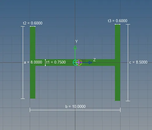
img:I-cross section beam element
- for bar go to create→standard section→optistruct→cross.And give the dimesnion.
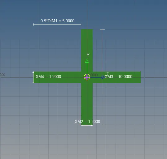
img:cross bar element
- we have to create the RBE2 element on the first hole(a):1D→Rigid→ and select the nodes and element in where we want to create ROD element.
- we have to create the RBE3 element on the first hole(b):1D→RBE3 → and select the nodes and element in where we want to create BEAM element.
- we have to create the RBE3 element on the first hole(c):1D→RBE3 → and select the nodes and element in where we want to create BAR element.
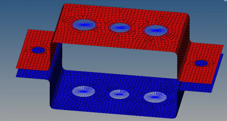
img:after creating RBE2 and RBE3
- after creating the RBE2 and RBE3 links cfeate the element to connect the two nodes inbetween each hole inorder to create the ROD,BAR,BEAM.
- Go to rod→ node(select the each node on the either side of the bracket)→ element type(CROD) and then click tab button.
- for second hole(b),go to bar→ node(select the each node on the either side of the bracket)→ element type(CBEAM) and then click tab button.
- for third hole(c),go to the bar→ node(select the each node on the either side of the bracket)→ element type(CBAR)and then click tab button.
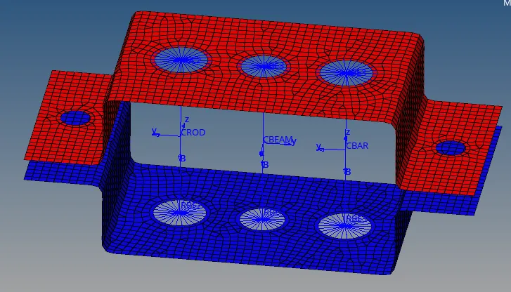
img:elements are creted by joing two nodes.
- once the element has been created,assign property to each of the element,By right click on the model view,go to create→ property→ and select the card image and select material for each element.
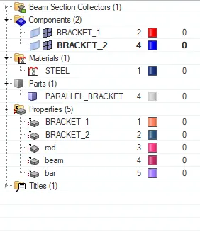
img:property assign to the each element
- Card name for ROD : CROD
- Card name for BEAM: CBEAM
- Card name for BAR : CBAR
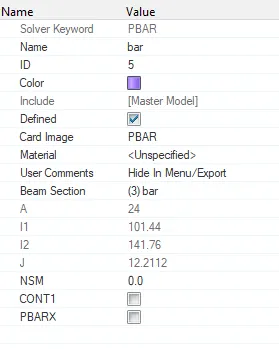
img:property for BAR element
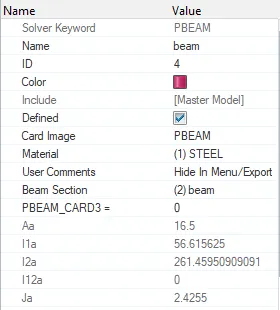
img:property for BEAM element
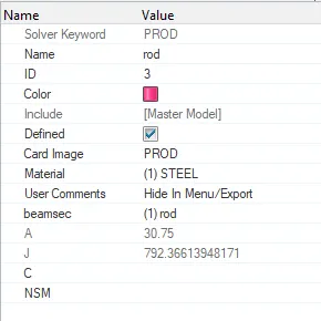
img:property for BAR element
- once the property has been assigned we can see the cross section for each of the element by clicking I-D detailed element representation.
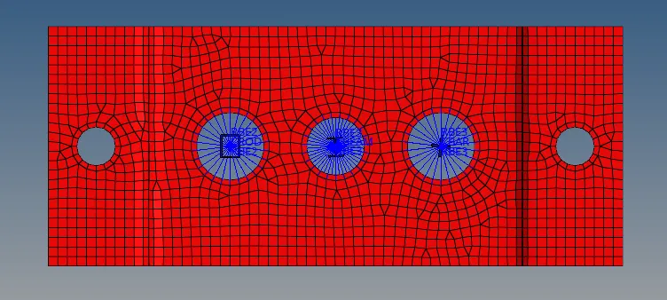
img:after assign the property for the elements.
- we have to create the RBE2 element on the hole(d,e,f) and apply mass of magnitude 10.
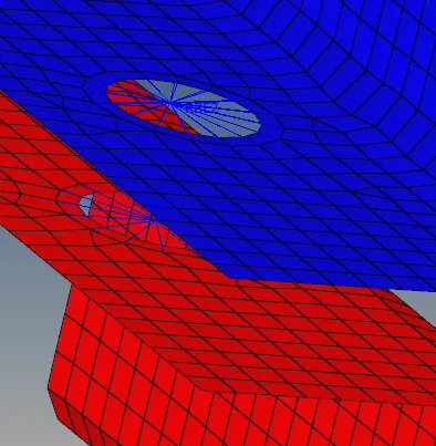
img:creating RBE2 element on the hole(d,e,f)
- after creating RBE2 element assign the mass of magnitude 10 on the node of each element:geometry→masses→create→enter the mass→select thre property→element type→create.
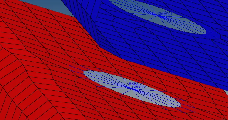
img:adding mass on the each node
- create spring element in between RBE2 link on the either side of the bracket.go to 1D→springs→select the node on the each (parallel side) on the bracket→property→element type and click tab button.
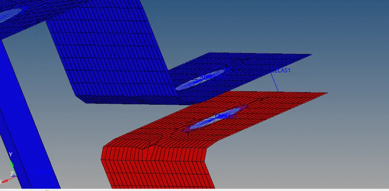
img:spring created on the right side of the parallel bracket
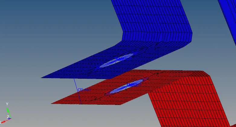
img:spring created on the left side off the paralle bracket.
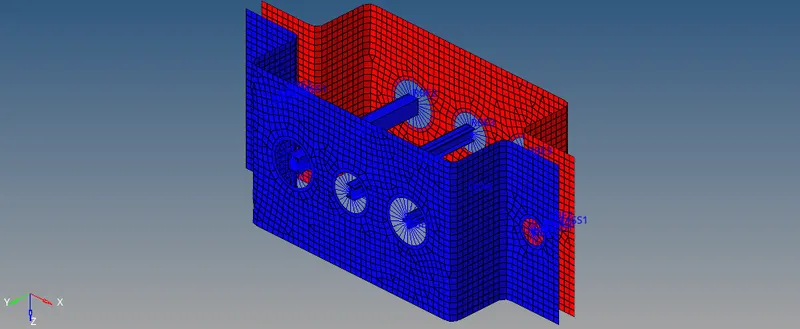
img:Final model of the parallel bracket
Result and conclusion:
- extracted the mid surface on the either side of the bracket.
- Created material and the property for each bracket and assigned.
- Created RBE2 and RBE3 on (e,d,b,c) and (a).
- Created 1D element such as BAR,BEAM,ROD on the top of the three holes(a,b,and c)
- All the three 1D element are created as per the given dimension and Degree of freedom(DOF).
- Added mass of magnitude of 10 each on the either side(d and e) cross section of the bracket.
- Added spring element on either side og the bracket(e,d)
outcome:
- learned to create 1D elements such as rod,beam,bar and also learn how to extract the midsurface and meshing on the mid surface.
- learned how to assign material and property for each component.