Week 4-1D Element Creation Challenge
AIM: Mesh the given component with the given elemental size and create 1D elements on that component with given cross-section and DOFs.
GIVEN:
a. Rod element:- Translational DOF should be Constrained with RBE2 link
Cross-Section: BOX- Dimension a= 12 mm
dimension b=10 mm
Thickness t= 0.75 mm
b. Beam element:- All DOF should be constrained with RBE3 link
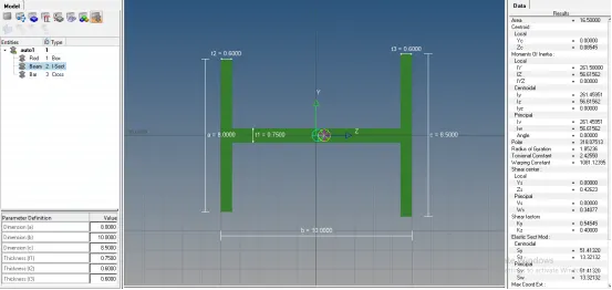
Cross-Section: I Section- Dimension a= 8 mm
Dimension b= 10 mm
Dimension c= 8.5 mm
Thickness t1= 0.75 mm
Thickness t2= 0.6 mm
Thickness t3= 0.6 mm
c. Bar element:- Constrain only x and y DOFs With RBE3 link
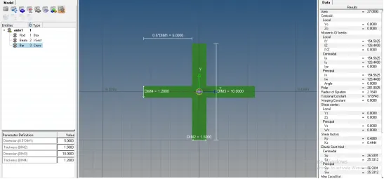
Cross-section: X section- Dimension DIM1= 5 mm
Thickness DIM2= 1.2 mm
Dimension DIM3= 10 mm
Thickness DIM4= 1.2mm
d & e. Apply the mass of magnitude 10 with the RBE2 link
f. Join the two components with Spring elements.
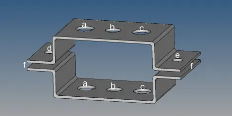
OBJECTIVE: The objective of this challenge is to create the mesh on the given component with the given elemental size and create 1D elements on that component with given cross-section and DOF.
DESCRIPTION: 1D elements are basically line shaped elements which are created by two nodes. They are used when one of the dimensions is comparatively very large than the other two. Bar and beam elements are considered as One Dimensional elements. These elements are often used to model trusses and frame structures. Bar is a member which resists only axial loads. A beam can resist axial, lateral and twisting loads. A truss is an assemblage of bars with pin joints and a frame is an assemblage of beam elements. Examples of 1D elements are RBE2, RBE3, Rod, Bar, Beam, Spring elements.
PROCEDURE:
1. Firstly import the model in hypermesh software and open it following the given steps: Go to Import geometry and select the file type as ‘iges’. Then choose the file and click on import option. The model gets open in the software.
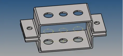
2. After opening the model, extract the mid surface of the part using Geometry>midsurface. Choose the auto midsurface option and select all the surfaces. Then click on extract option. Midsurface gets created.
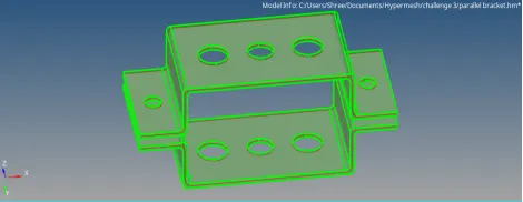
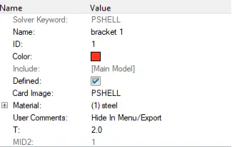
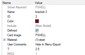
3. Then assign the material and properties to the midsurfaces of both parts separately. Also assign thicknesses to both the parts.
4. After midsurface is generated for each of the component , delete all the solids present in the component.
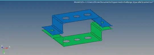
5. Then create washer splits around the holes.
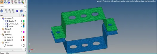
6. Now proceed for meshing the component. Here meshing will be done by following the steps given below: Go to 2D> automesh option and enter the given element size as 5 units. Then choose the mesh type as required and select all the surfaces. Then execute the meshing by clicking on mesh option.
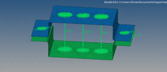
7. Now we create 1D elements on that component with given cross-sections and DOFs.
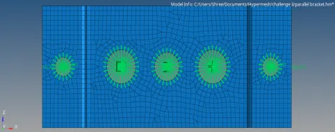
a. Rod element:-RBE2 elements using 1D>rigids on holes mark as ‘a’ and restrict translational DOFs in X, Y & Z directions.
b. Beam element:- RBE3 elements using 1D>rbe3 on holes mark as ‘b’ and restrict all DOFs in X, Y & Z directions.
c. Bar element:- RBE3 elements using 1D>rbe3 on holes mark as ‘c’ and restrict all DOFs in X & Y directions.
d. RBE2 link on holes mark as ‘d & e’ using 1D>rigids.
e. Spring elements at points mark as ‘f’ using 1D>springs.
8. Now we apply mass of magnitude 10 units at ‘d & e’. For that go to 1D>masses and select the nodes. Enter the value of mass and select the element type as ‘CMASS1’. Then click on create. Mass got applied.
9. Now we create hyperbeams for rod, beam and bar. For that go to 1D>Hyperbeam>standard section and select the type as required.
a. For case one, create the standard section type as ‘thinwalled box’ and enter the dimensions.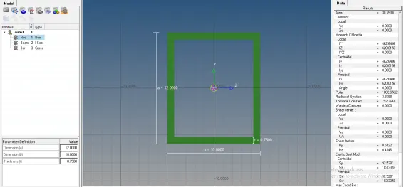
b. For case two, create the standard section type as ‘I-section’ and enter the dimensions.
c. For case three, create the standard section type as ‘cross-section’ and enter the dimensions.
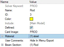
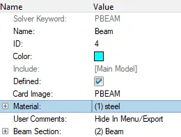
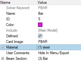
10. Once cross sections are created, we create properties and assign these properties to each of them shown below:
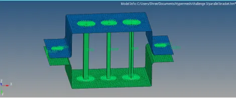
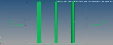
2D Detailed Elemental Representation of model:
LEARNING OUTCOMES:
1) Performing this challenge enables to use different tools in the software.
2) Learn to extract the midsurface and create mesh on the given component.
3) Learn to create 1D elements like rigids, RBE3, rods, bars, beams, springs etc. with require DOFs.
4) Learn to create different cross sections for 1D elements and also learn to assign properties for them.
5) Learn to apply mass on different links.
CONCLUSION: After extracting the midsurface and generating mesh on the given model, 1D elements successfully created on the given component with given cross section and DOFs.