Week 4-1D Element Creation Challenge
AIM:
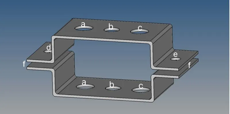
• To generate mid-surface for the given Bracket and to mesh the bracket with element size of 5 units.
• To create 10 bar, Rod and Beam element from the given data.
• To assign thickness, material and property to the components
OBJECTIVE
THEORY
RBE2 Panel :
A rigid part is part created during a area between 2 nodes of a model wherever a rigid affiliation is desired, within the RBE2 link, Load are distributed equally for all nodes. Rigid link components may be created with dependent nodes connected to part as a group. If a rigid link with a dependent node-set is deleted, the associated node-set is additionally deleted. If the dependent node-set in any panel is deleted, the connected rigid link part is additionally deleted. Dependent node sets square measure mechanically created once rigid link components square measure created. A node-set created within the Sets panel may be connected as a group of dependent nodes to a rigid link part freelance node.
RBE3 Panel :
RBE3s square measure interpolation constraint components, wherever the motion of a dependent node is outlined because the weighted average of the motions of a bunch of freelance nodes. The dependent degrees of freedom and coefficient factors may be nominative or mechanically calculated supported the pure mathematics. RBE3s square measure generally accustomed distribute masses applied to the dependent node amongst the chosen freelance nodes within the RBE3 link, Load distribution are varied.
Masses Panel:
Use the lots panel to form mass components. A mass part rests on a node and is employed to represent mass.
Rods Panel :
Use the Rods panel to form rod components. A rod part is part created during a area between 2 nodes of a model wherever rod properties square measure desired. the 2 nodes square measure associated with one another supported the properties of the rod part connecting them.
Hyperbeam Panel:
Use the HyperBeam panel to form beam cross-sectional entities that you just will use to change advanced parts of your model into straightforward bar components. The HyperBeam panel is organized into many subpanels. every subpanel covers a special sort of beam section, apart from the a lot of general edit section and section utils (utilities) subpanels. It will move freely between subpanels, performing on one sub panel won't be lost if you turn to a special subpanel.
Springs Panel :
Use the Springs panel to form spring components. A spring part is part created during a area between 2 nodes of a model wherever a spring affiliation is desired.
PROCEDURE
-
First step is to import the IGES model. For importing the model,go to FILE>GEOMETRY>FILE TYPE>IGES>IMPORT.
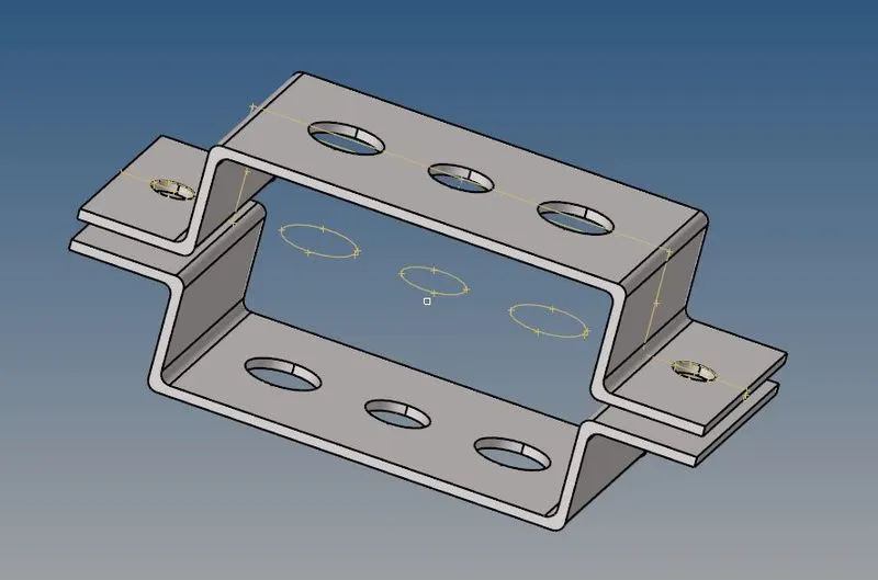
- Now to extract the mid surface of the Bracket proceed with the model to the mid surface by selecting Geometry >> mid surface >> and select the elements that you want to take mid surface.
- In this model, we have two brackets and both are the same as each other while we taking the mid surface in hypermesh there are 4 options available to us. They are shown below in the picture.
MId surface extraction option:

1 .MId surface using offset+plane+sweep
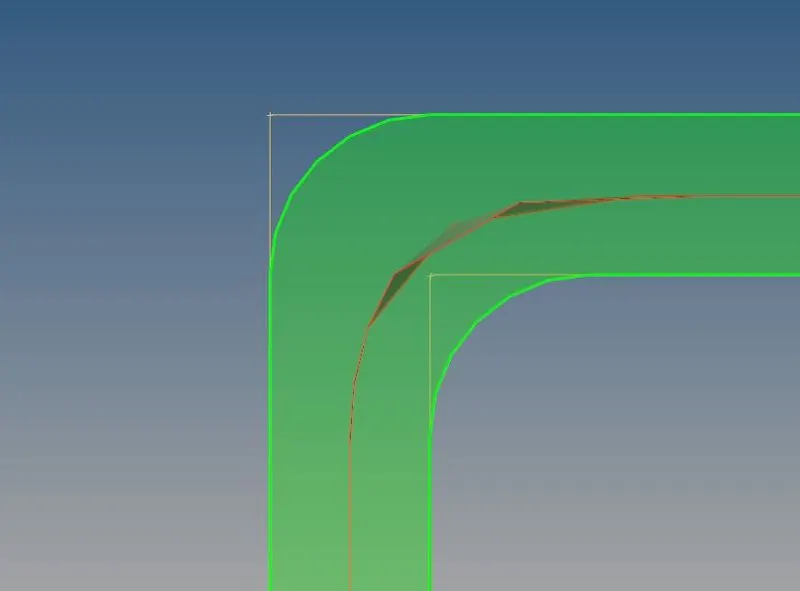
2 . Mid surface using offset + plane
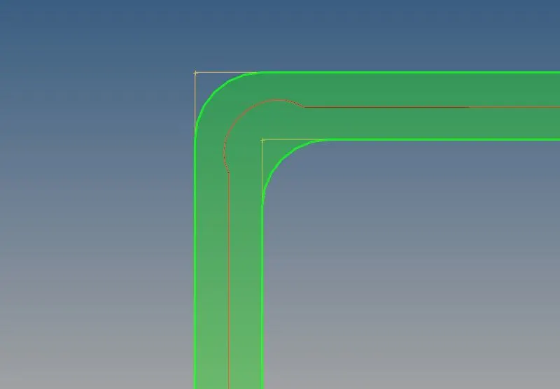
3 .Midsurface using offset
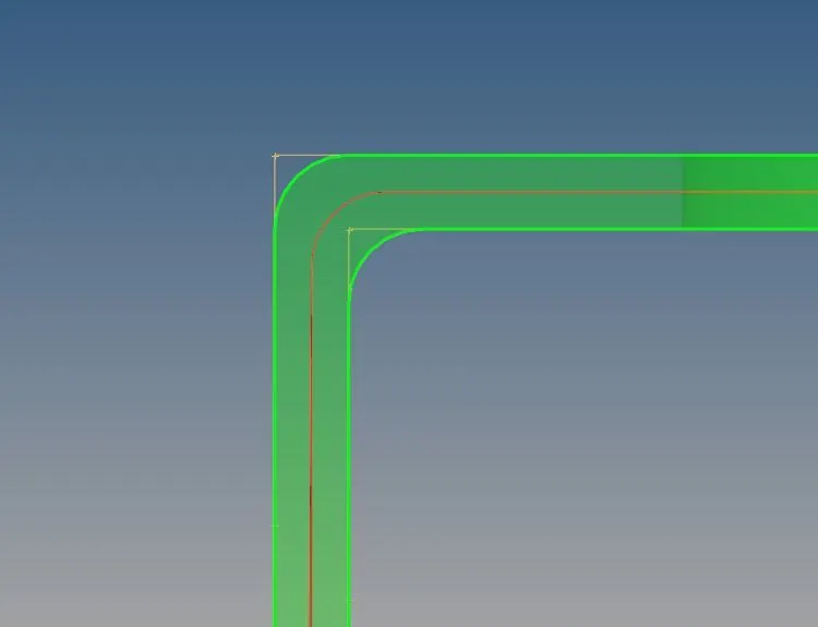
4 . MIdsurface using skin offset
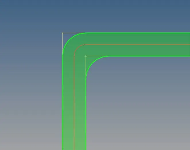
-
I have tried all these 4 options and I choose skin offset to extract the midsurface. The remaining option did not capture the edges properly .Edge capturing is important because it can later lead to irregular mesh flow and quality issues during meshing .
- Now remove all the solids using the delete option.also remove the remaining components other than two midsurfaces.
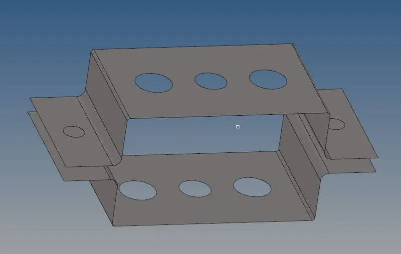
- After the mid surface is generated for the whole component. We can divide mid surfaces into n number of components.
- 1st we need to create the components. I have created Bracket_1 and Bracket_2.
- It will make Bracket_2 as the current component (right-click on the component and make it as current). Now go to tools >> organize >> select
surfaces >> click on the move. - similarly organise the 2nd midsurface to Bracket_2 .
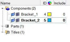
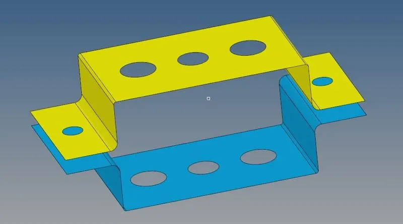

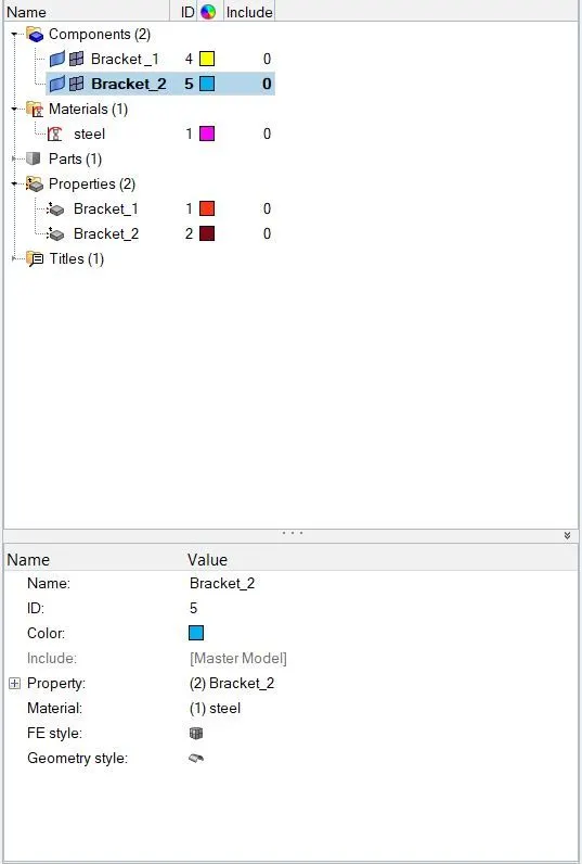
- Produce Steel material card and property card for both the brackets.[right click on mouse + create + material and property choice]
- select card as MAT1 for material which is nothing but steel.
- For properties select card image as PSHELL, as these are surfaces .
- assiign steel as thier material.
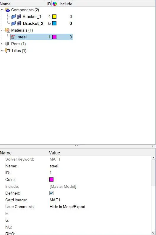
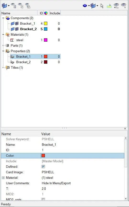
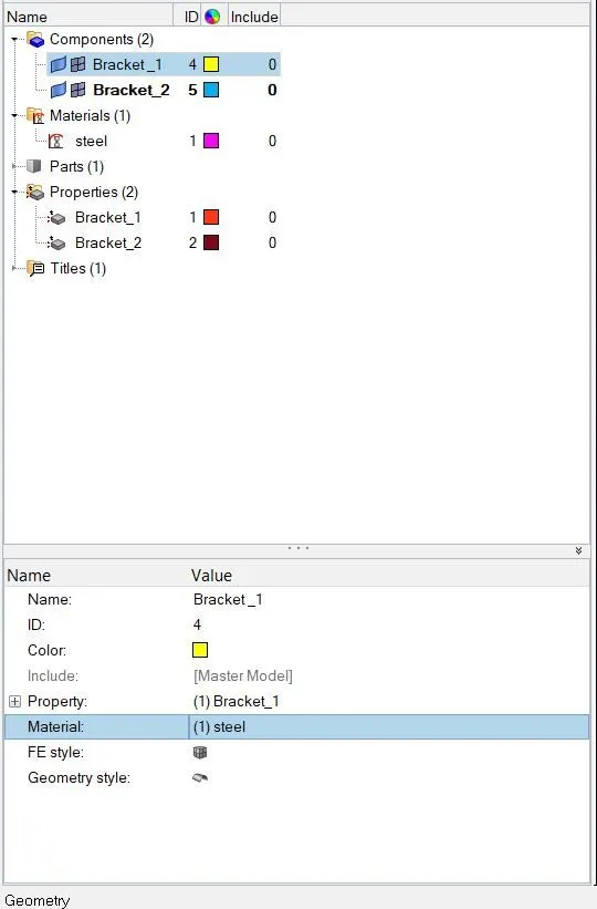
Now go to component section and assign property ,then it will automatically take the material. Therefore ,material and properties are assigned to Bracket_1 and Bracket_2 .
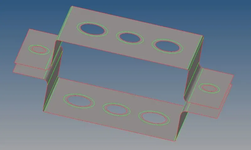
- For creating washer split at the holes so as to get a better mesh near the holes ,Use Washer split choice and make a washer as 5mm on every pinholes.[ GEOMETRY + QUICK EDIT + WASHER SPLIT]
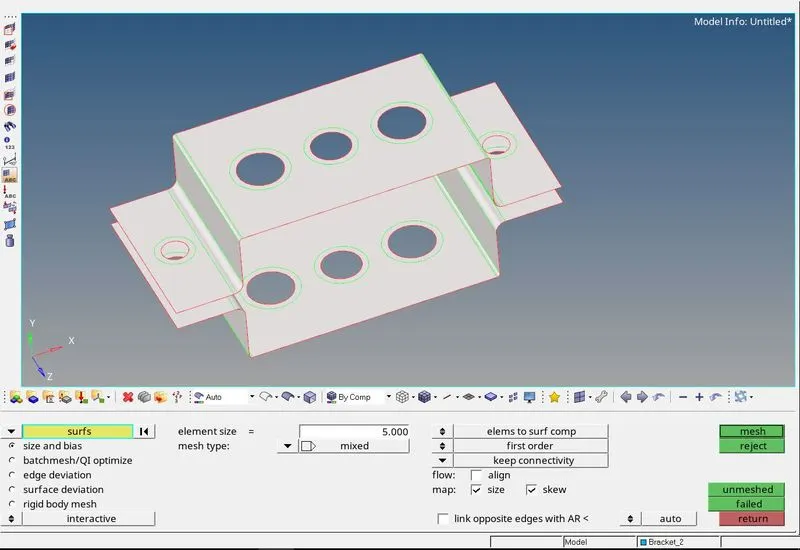
- Now create the mesh for both the brackets ,
Got to2D> AUTOMESH > SURFS > ALL > ELEMENTSIZE=5 > MESH TYPE MIXED > MESH
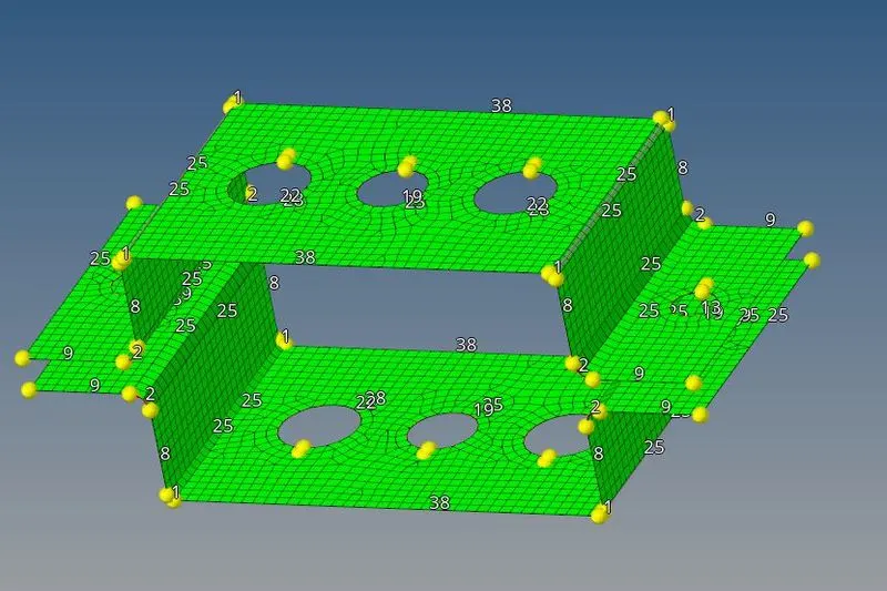
THE meshed bracket is shown below:
-
Now for washer element checks for the same no of nodes at the inner and outer edge . To increase the no of nodes left click on the number displayed ,to reduce the no of nodes right click on the no displayed
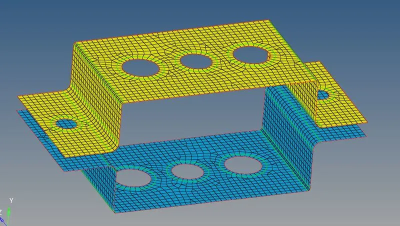
-
Now make links as the current component and start creating RBE2 and RBE3 elements
Go to 1D > RIGIDS > CREATE > MULTIPLE NODES >CALCULATE NODES> NODES BY PATH >SELECT THE NODES AT THE HOLE REGION >TRANSITIONAL DOF CONSTRAINED > CREATE
This will create RBE2 cluster elements .Create RBE2 element at the hole provided in the drawing ie at a,d and e.
RBE2 at a -
RBE2 at a d and e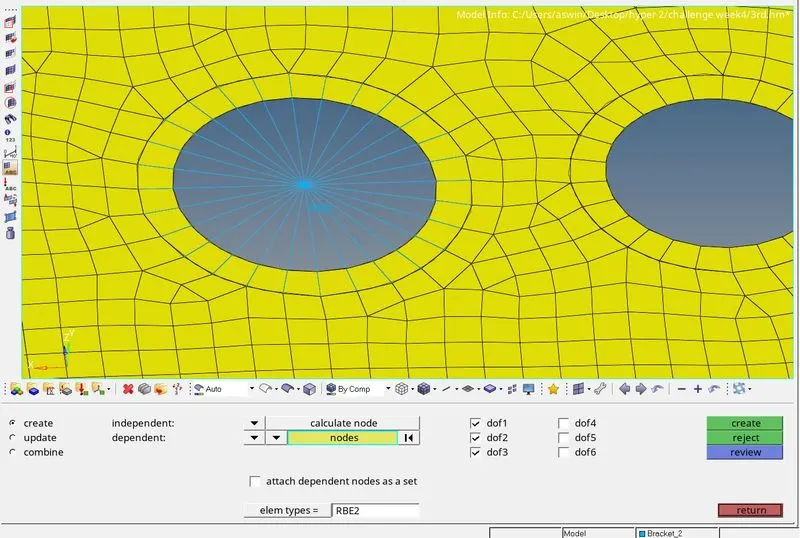
-
Now similarly create RBE2 element at Bracket_2
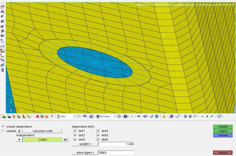
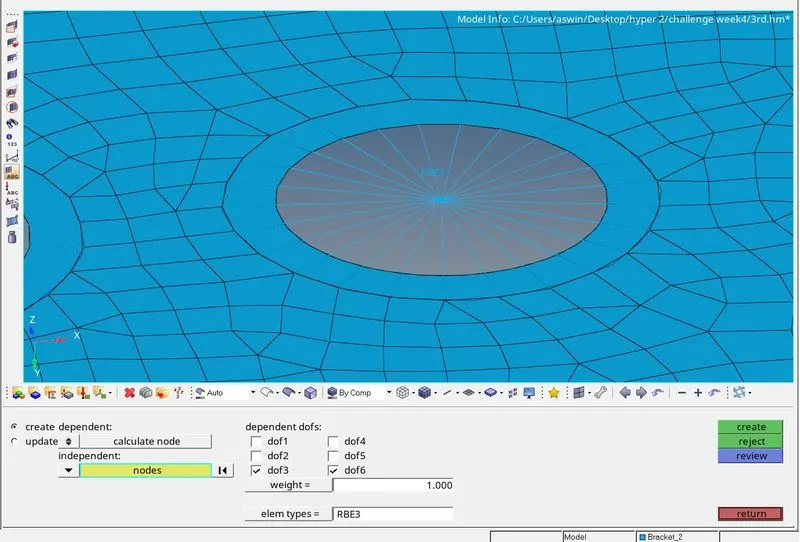
Now to create RBE3 element go to 1D>RBE2>CREATE>NODES BY PATH>SELECT THE NODES >CONSTRAIN DOF>CREATE
This will create RBE3 elements at b and c and constrain the DOF according to the given data.
RBE3 at b
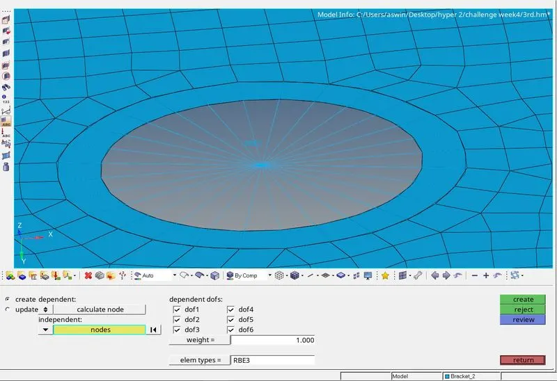
RBE3 at c
- Now we can create cross sections using hyper beam
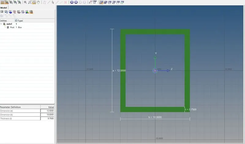
• Now create Box Section at "a" with given dimensions (a 12 mm, b=10 mm, Thickness t=0.75 mm)
• Go to 1D >> Hyper beam >> Standard section >> select section library and type >> Create.
• Then it will take you to hyper beam, where you can edit all the dimensions of the section which we have given.

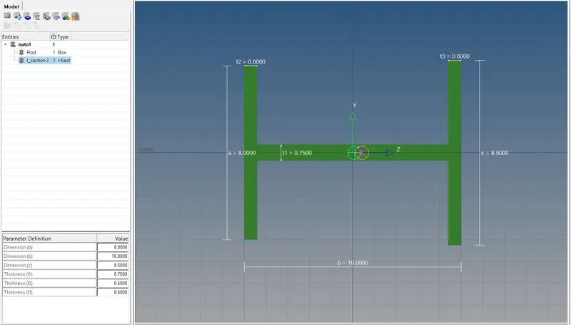
similarly we can create cross sections for I section and X section according to the required dimesnion.
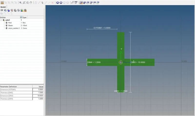
- Now we can create some !D elements like rod bar and beam .
- for creating a rod 1D> ROD>SELECT NODES > SELECT ELEMENT TYPE AS CROD
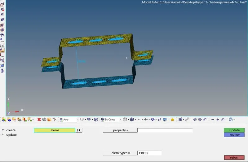
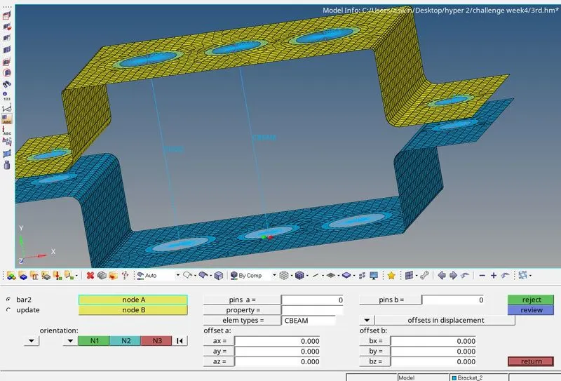
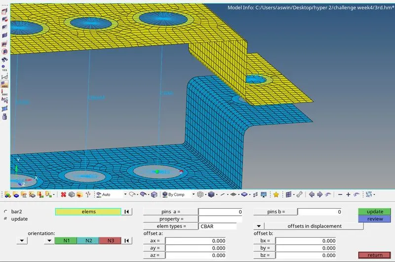
Similarly we ca create beam at b and bar at c using BAR option in 1D .
- Now we can create 3 sepertate properties for rod , bar and beam.
- Now assign the Box,I and X sections to each of the properties .
Assingining box to rod Assigning bar to X section Assigning beam to I section
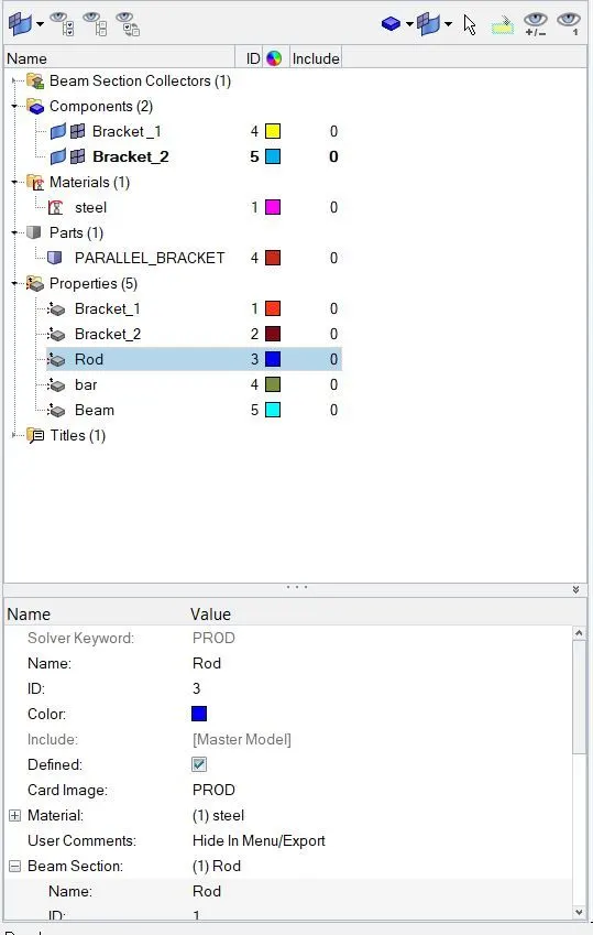
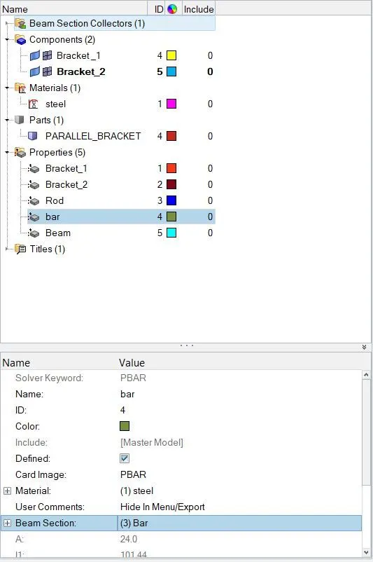
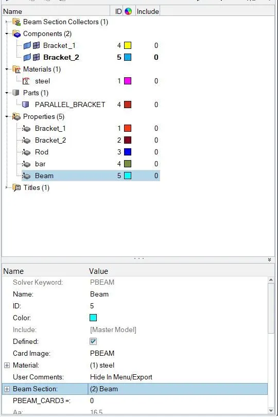
- Now we can update each of the properties to Rod beam and bar. ROD/BAR > UPDATE > PROPERTIES > SELECT THE PROPERTY > UPDATE .
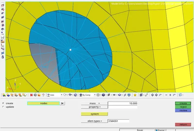
- now we can Apply a mass of magnitude 10 at d and e
1D > masses > select nodes > element type as CMASS1 > magnitude= 10 > create
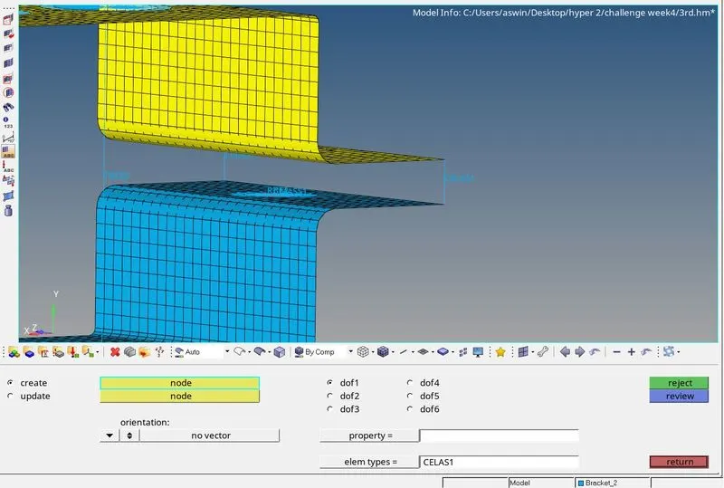
- Now we can join the two components using a spring section at the 2 ends of the bracket at f .
1D > SELECT THE NODE > ELEMNT TYPE AS CELAS1 > CREATE .
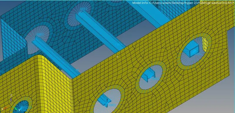
- Now switch the view to 1D DETAILED ELEMENT REPRESENTATION we can see the cross section the rod bar and beam sections correctly as shown below.
RESULT
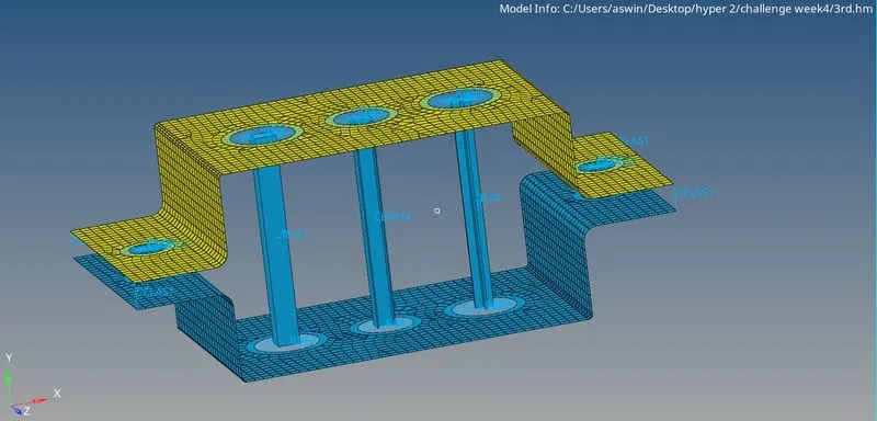
Created 1D elements on the given component with given cross-section and DOF.
a-Rod element Created with translational DOF contrained and RBE2 link.
b- Beam Element Created with all DOF constrained and RBE3 link.
c-Bar Element Created with x &Y DOF contrained and RBE3 link.
d&e Mass added on the Master node of RBE2 link.
f-Two Components were joined with Spring Elements.
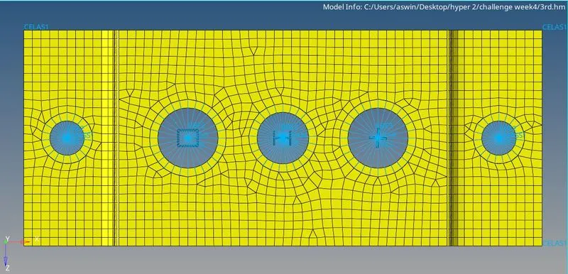
TOP VIEW :
CONCLUSION
1.I have learnt the extraction of mid surface and meshing
2.Creation of the 1D elements(rod,bar, beam) and cross section creation
3.And also learnt the how to assign property and material to componet