Week 4-1D Element Creation Challenge
Week 4-1D Element Creation Challenge
1. Aim
Mesh the Given component with the Size of 5 Units. Create 1D elements on the following component with the given cross-section and DOF
a. Rod element:- Translational DOF should be Constrained with the RBE2 link
Cross-Section: BOX- Dimension a= 12 mm
dimension b=10 mm
Thickness t= 0.75 mm
b. Beam element:- All DOF should be constrained with the RBE3 link
Cross-Section: I Section- Dimension a= 8 mm
Dimension b= 10 mm
Dimension c= 8.5 mm
Thickness t1= 0.75 mm
Thickness t2= .6 mm
Thickness t3= .6 mm
c. Bar element:- Constrain only x and y DOFs With RBE3 link
Cross-section: X section- Dimension DIM1= 5 mm
Thickness DIM2= 1.2 mm
Dimension DIM3= 10 mm
Thickness DIM4= 1.2mm
d. & e. Apply the mass of magnitude 10 with the RBE2 link
f. Join the two components with Spring elements
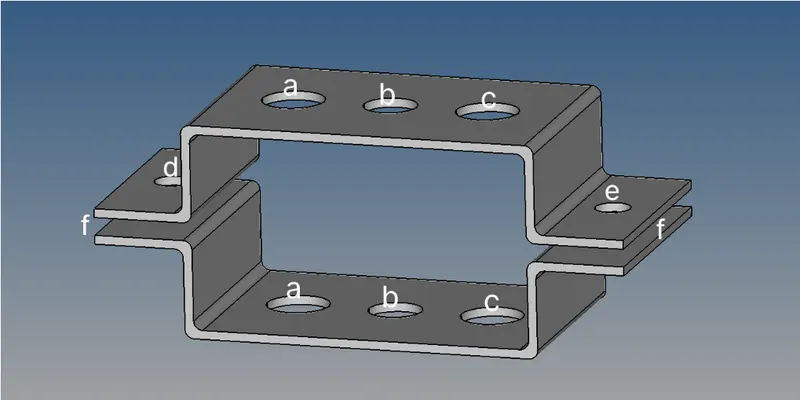
Fig 1: Reference of The Model
2. Objective
- Import the given IGES geometry to Hyper Mesh
- Extract the mid-surface of the brackets.
- Create Components, Materials, Parts and Properties according to the model.
- Create 1D elements with mentioned cross-sections and dimensions
- Apply the mass of the given value to the specified areas.
- Join the brackets with spring elements.
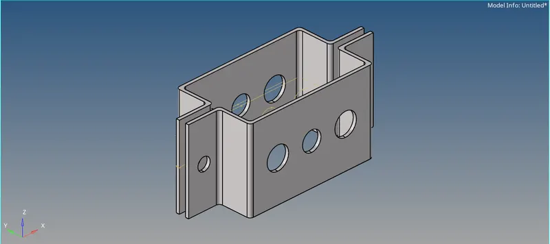
Fig 1: Isometric View of The Model
3. Procedure
Step 1: Importing and Mid-Surface Extraction
First We have to import the file to hyper mesh. Here, the file is in IGES format.
- File >> Import >> Geometry >> Browse the file location >> Select The File >> Import.
After a quick auto cleanup, and washer splits creation, the geometry is ready for extraction of mid-surface. The mid-surface of the model is created by,
- Geometry >> Mid surface >> Auto mid surface >> Target Element Size = 5 Units >> Select The Surface >> Extract.
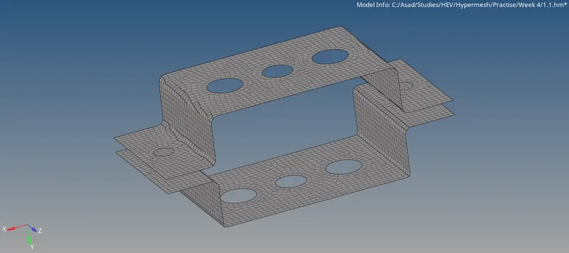
Fig 2: Mid Surface of The Model
Here, the mid surface of brackets is saved in a component separately.
Step 2: Creating Components, Properties, and Materials.
For 1D element creations, initially, we have to create and assign components. For creating components,
- Model View >> Element & Geometry >> Right Click >> Create >> Componets >> Rename >> Ok.
Similarly, the material and the properties can be created. For Material
- Model View >> Element & Geometry >> Right Click >> Create >> Material >> Rename >> Ok
While Creating the material, the Card Image is to be changed. In this case, there is no specified card image, so Card Image is taken as 'MAT 1'. For properties,
- Model View >> Element & Geometry >> Right Click >> Create >> Properties >> Rename >> Ok
Also, these properties have separate Card images as well. Assign materials to these properties
| Properties | Card Image | Material |
| Bracket | PSHELL | Steel (MAT 1) |
| MS | PSHELL | Steel (MAT 1) |
| Rod | PROD | Steel (MAT 1) |
| Beam | PBEAM | Steel (MAT 1) |
| Bar | PBAR | Steel (MAT 1) |
| Spring | PELAS | |
| Mass | PMASS |
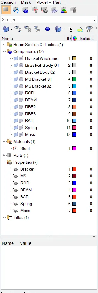
Fig 3: Components, Material and Properties.
Step 3: Creating 1D Elements
The 1D elements are constructed by using a Hyperbeam. The 1D elements (Bars, Rods, Beams, etc) have specific cross-sections. For this,
- 1D >> Hyperbeam >> Standard Selection >> Standard Selection Library (HYPER BEAM) >> Standard Section Type (Type Of Cross Section) >> Give Dimensions >> Ok.
Here, we need to create 3 types of cross-sections.
For 'Box Section', Standard Section Type = Thinwalled Box
For 'I Section', Standard Section Type = Standard I Section
For 'Cross Section', Standard Section Type = Cross
We can also construct these elements in hyper beam interface by
- Hyper beam Interface >> Right Click on Entities >> Create >> Standard Section >> Opistruct >> Select Section Type >> Give Dimensions.
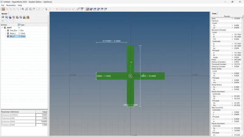
Fig 4: X Section
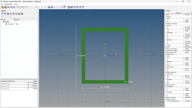
Fig 5: Box Section
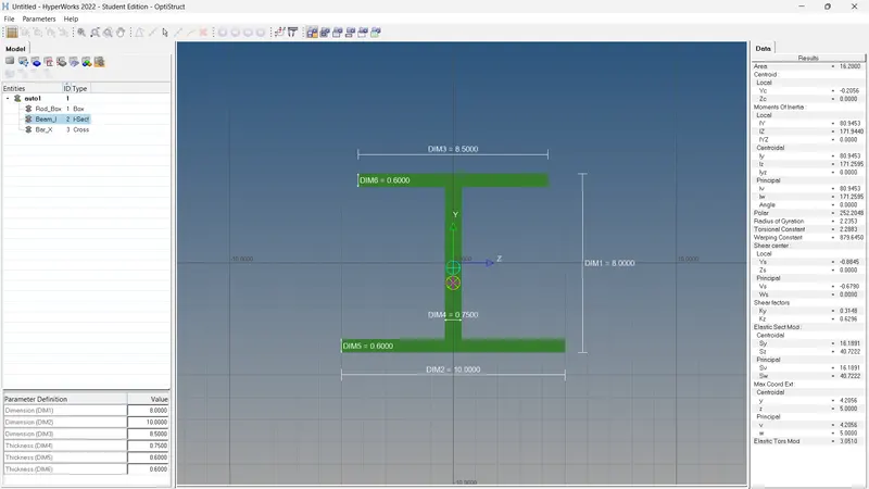
Fig 6: I Section
Assign these beam sections to the following properties
| Property | Beam Section |
| Rod | Box Section |
| Beam | I Section |
| Bar | X Section |
Step 3: Creating RBE2 and RBE3 Links and Assign the DOF Constraints
For creating RBE2 links,
- 1D >> Rigids >> Select Nodes (By Path) >> Select DOF Which to be constrained >> Create
For Creating RBE3 links
- 1D >> RBE3 >> Select Nodes (By Path) >> Select element type = RBE3 >> Select DOF Which to be constrained >> Create
("dof1, dof2, dof3 = Translation in x, y and z axis" and "dof4, dof5, dof6 = Rotation in x, y and z axis")
Each set of links has different DOF constraints. So try to save links in different components.
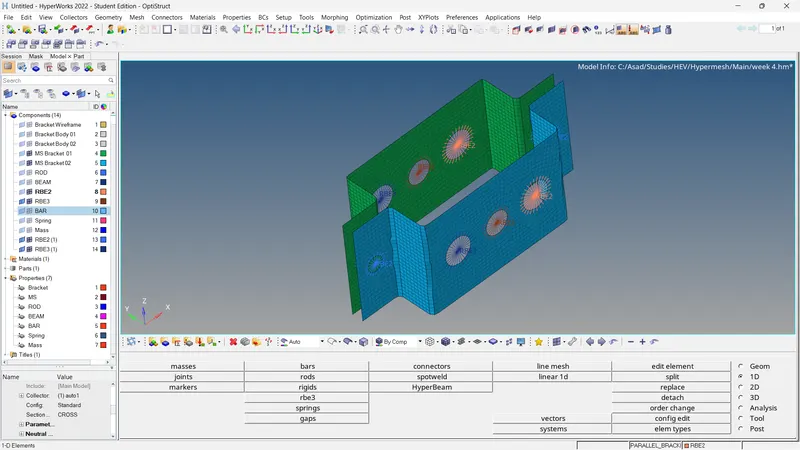
Fig 7: RBE2 and RBE3 Links
Step 4: Construction Of Rod Element
According to the objective the Rod element is created by connecting RBE2 elements having translational DOF constraints.
- 1D >> Rods >> Create >> Select Master Nodes Of Both RBE2 Links >> Element Type = CROD >> Property = Rod (Card Image = PROD)
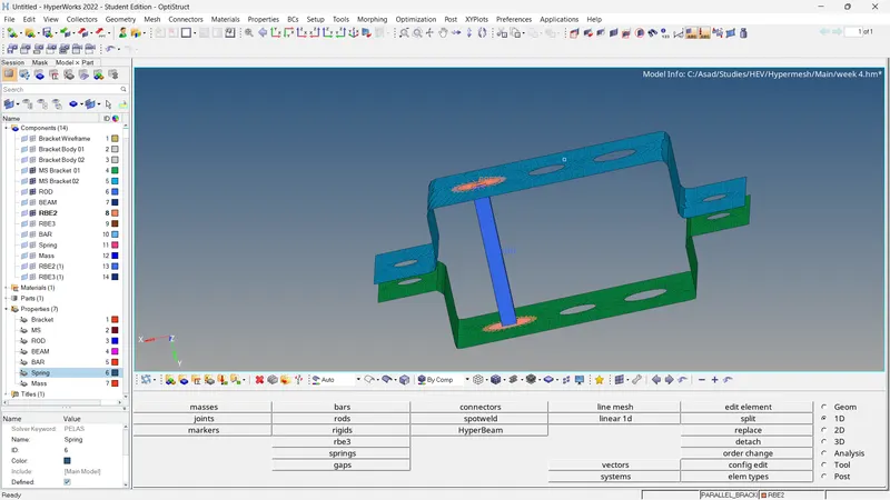
Fig 8: Rod Element
Step 5: Construction Of Bar and Beam Elements
The Beam element is created by connecting RBE3 elements having all DOF constraints.
- 1D >> Bars >> Create >> Select Master Nodes Of Both RBE3 Links >> Select Orientaion Nodes N1, N2, N3 >> Element Type = CBEAM >> Property = Beam (Card Image = PBEAM)
The Bar element is created by connecting RBE3 elements having DOF constraints in the x and y-axis.
- 1D >> Bars >> Create >> Select Master Nodes Of Both RBE3 Links >> Select Orientaion Nodes N1, N2, N3 >> Element Type = CBAR >> Property = Bar (Card Image = PBAR)
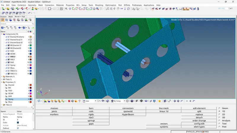
Fig 9: Beam and Bar Elements
The 1D representation can be visible by turning on the "1D Traditional and Detailed Element representation"
Step 6: Assigning Of Mass
The mass is applied on two RBE2 links on the edges of bracket 01.
- 1D >> Masses >> Select Master Nodes Of Both RBE2 Links >> Mass = 10 Units >> Property = Mass (Card Image = PMASS) >> Element Type = CMASS1 >> Create
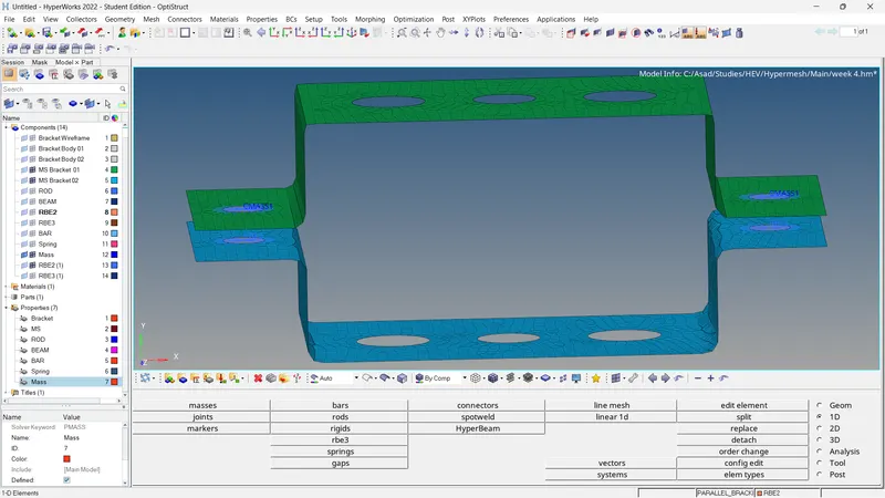
Fig 10: Mass Representation
Step 7: Creating Spring Elements
The two brackets are connected by spring elements by creating springs on 4 end nodes.
- 1D >> Springs >> Select Start Nodes and End Nodes >> Select dof Constarints (dof2) >> Property = Spring (Card Image = PELAS) >> Element Type = CELAS1 >> Create.
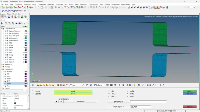
Fig 11: Springs
The 2D representation can be shown by turning on the "2D Traditional and Detailed Element representation"
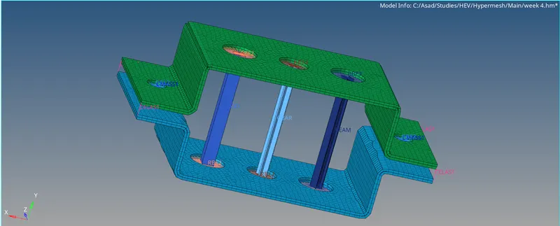
Fig 12: Final Result
4. Conclusion
- The File is imported and extracted mid-surface with mentioned target element length.
- The components, materials and properties are created and assigned the corresponding criteria and values.
- RBE2 and RBE3 links are created with mentioned constraints.
- 1D elements are created by joining corresponding rigid links.
- Create and assign masses on the following RBE2 links
- The brackets are connected using springs with the given criteria
5. Result
- For the model, 1D elements with the given cross-section and DOF is constructed.