Week 4-1D Element Creation Challenge
AIM:
Mesh the Given component with the Size of 5 Units.Create 1D elements on the following component with given cross-section and DOF
A. Rod element:- Translational DOF should be Constrained with RBE2 link
Cross-Section: BOX- Dimension a= 12 mm
dimension b=10 mm
Thickness t= 0.75 mm
B. Beam element:- All DOF should be constrained with RBE3 link
Cross-Section: I Section- Dimension a= 8 mm
Dimension b= 10 mm
Dimension c= 8.5 mm
Thickness t1= 0.75 mm
Thickness t2= .6 mm
Thickness t3= .6 mm
C. Bar element:- Constrain only xand y DOFs With RBE3 link
Cross-section: X section- Dimension DIM1= 5 mm
Thickness DIM2= 1.2 mm
Dimension DIM3= 10 mm
Thickness DIM4= 1.2m
D & E. Apply the massof magnitude 10 with the RBE2 linK.
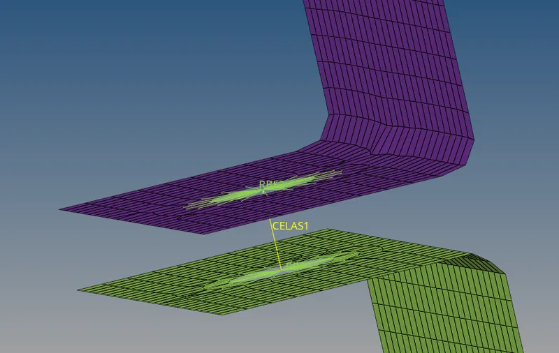
F. Join the two components with Spring elements
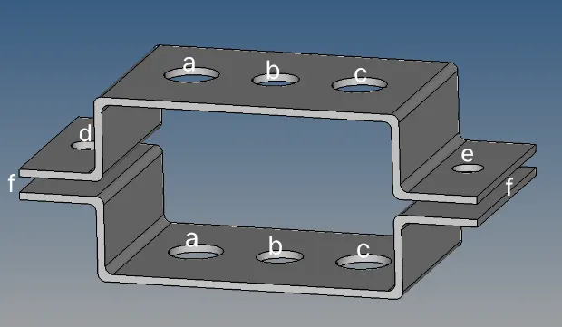
PROCEDURE:
- Import the given model by using Import geometry option
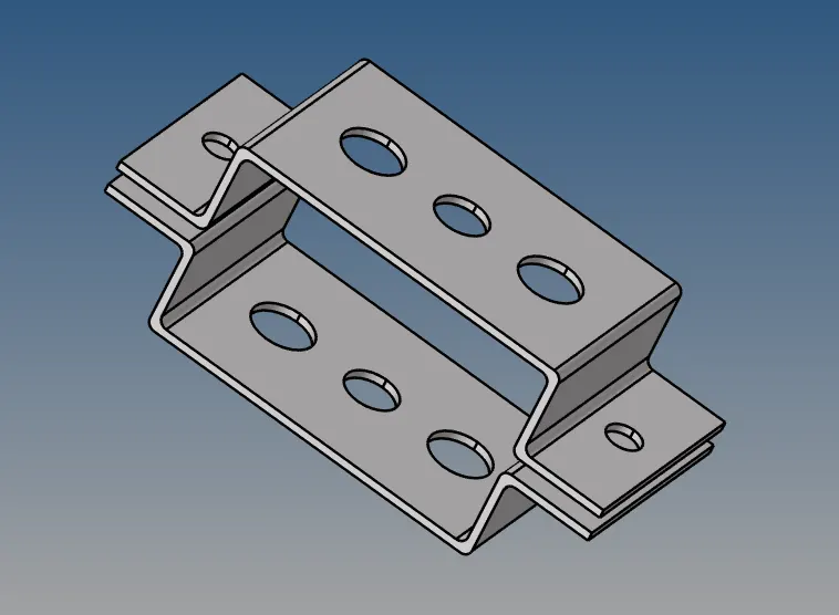
- Extract the midsurface for the given model
- Goto Geometry > midsurface
- Since the model is of uniform thickness, autoextraction is preferred
- Select the whole model and extract the mid
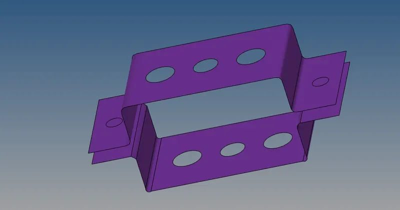
- since both the mid are generated in a single component
- we can seperate to two components, by creating a new component and move the mid
- For moving the midsurface to different component Goto Tool > Organise > move
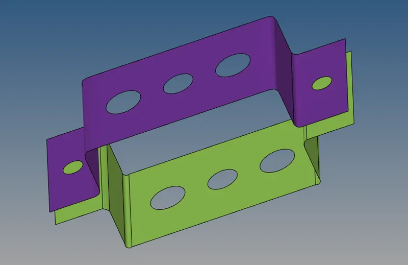
- Assign the material for the component as steel in the model browser.
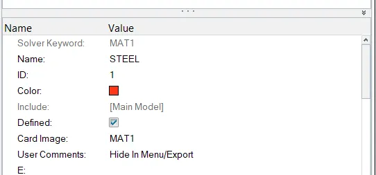
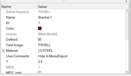
- Similalry assign properties for the components in the model browser
- Give card id as PSHELL , select the material as steel and provide thickness value
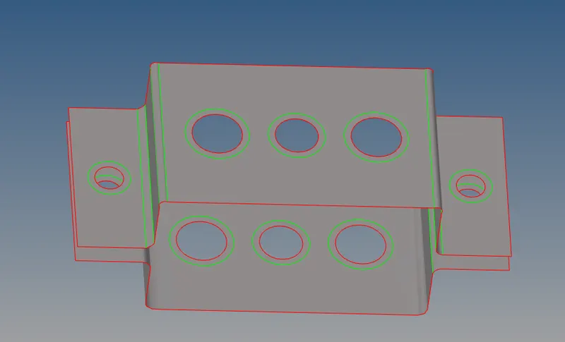
- Give washer splits fort the holes,Goto Geometry > Quickedit > Washer split
- provide offset value as 5mm and select the holes
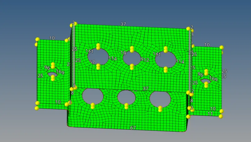
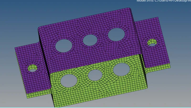
- Mesh the mid ,Goto 2D > AUTOMESH , give target element size as 5mm
- Adjust the nodes by matching the numbers after meshing
- Hide the surafaces of the component ,Goto model browser > components
- Connections:
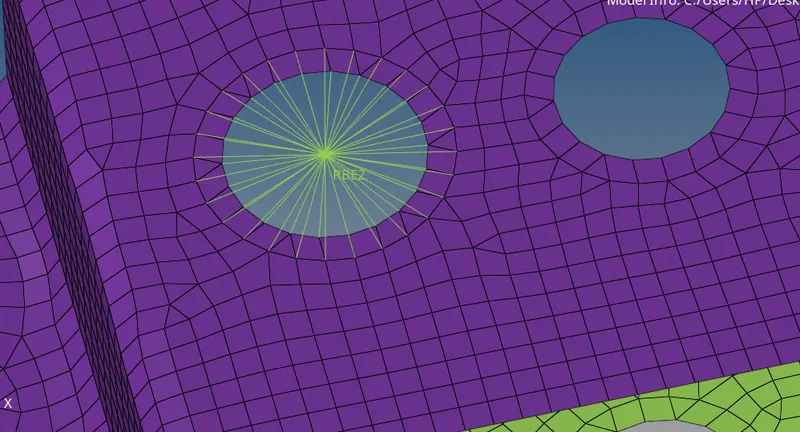
- For holes we use RBE2 and RBE3 elements in 1D module
- For creating RBE 2 elements ,Goto 1D module > Rigids > Elemnt type RBE2
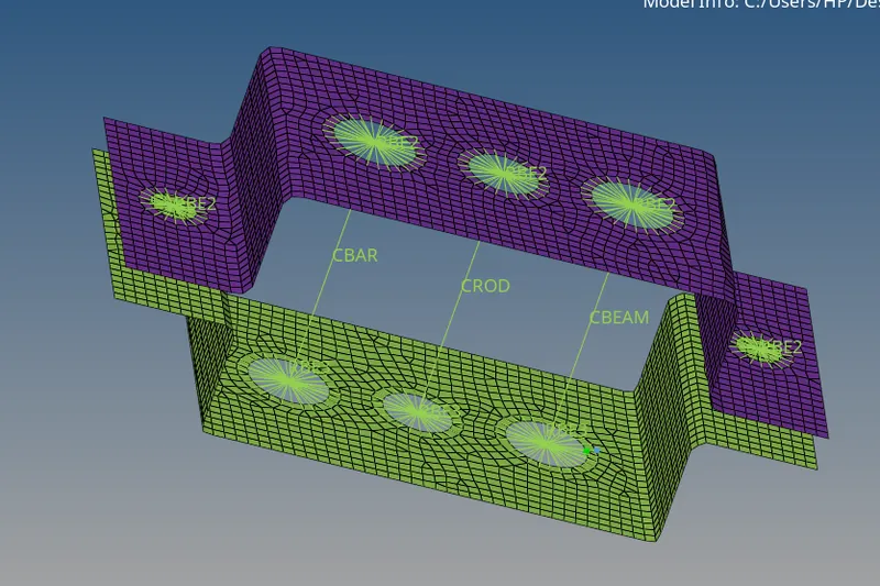
- After meshing Create 1D elements such as Bar ,Rod and Beam
- For Bar and Beam select element type CBAR and CBEAM respectively
- For Rods element type is CROD and select the nodes
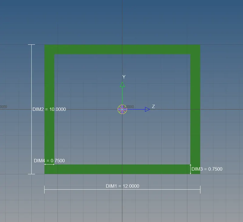
- Create cross sections for Bar ,Rod and Beam
- For creating cross sections goto hyper beams > create
- For rod:
- Cross-Section: BOX - Dimension a= 12 mm
Dimension b=10 mm
Thickness t= 0.75 mm
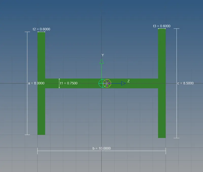
- For beam:
-
Cross-Section: I Section - Dimension a= 8 mm
Dimension b= 10 mm
Dimension c= 8.5 mm
Thickness t1= 0.75 mm
Thickness t2= .6 mm
Thickness t3= .6 mm
- For Bar:
-
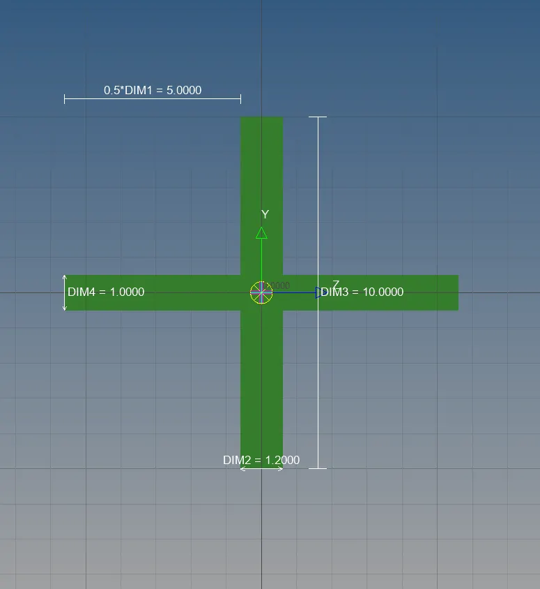
Cross-section: X section - Dimension DIM1= 5 mm
Thickness DIM2= 1.2 mm
Dimension DIM3= 10 mm
Thickness DIM4= 1.2mm
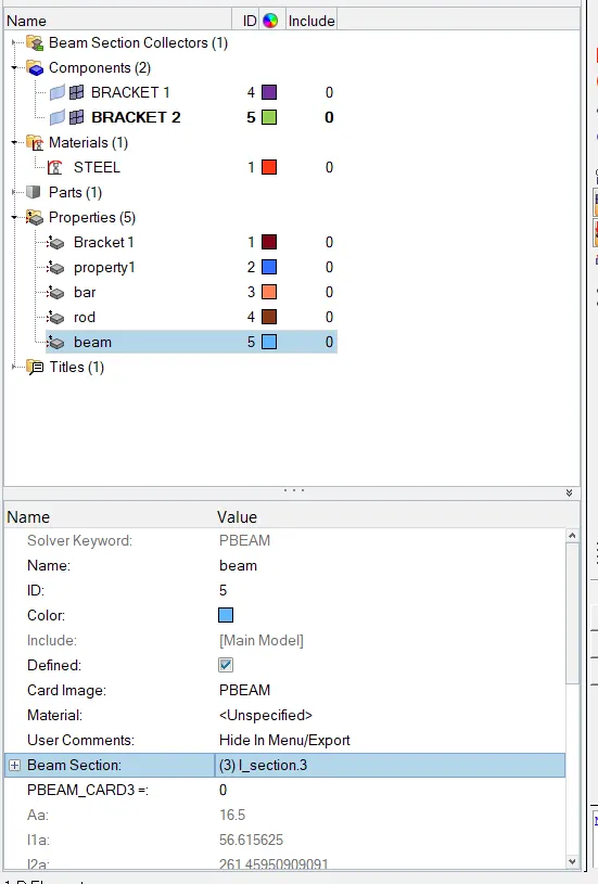
- Create new properties for the sections
- Use PROD, PBEAM, PBAR as property ID for Rod ,Beam and Bar respectively
- After creating properties, Update the 1D elements by selecting the property and matching them
- Mass is applied with the magnitude of 10 in RBE2 links
- spring elements are created as shown below
- Finally, Change from traditional 1D element representation to 1D detailed element represnetation
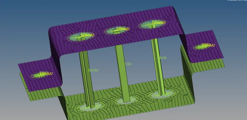
CONCLUSION:
- Mid-surface is taken for the given model , assigned material property and created new properties for the component.
- Provided washer splits to the holes and Meshed the mid with the given target element size
- The Holes has been connected with RBE2 & RBE3 elements.
- Created 1D elements like Rod,Bar,Beam and created cross section for them .
- Created new properties for the cross sections and updated the property with 1D elements
- The mass has been applied with the magnitude of 10 on RBE2 links
- The spring elements are created to join the two components