Week 4-1D Element Creation Challenge
Week 4-1D Element Creation Challenge
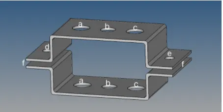
Objective:- To Mesh the Given component with size of 5 and create 1D element with given cross sections and DOF.
a. Rod element:- Translational DOF should be Constrained with RBE2 link
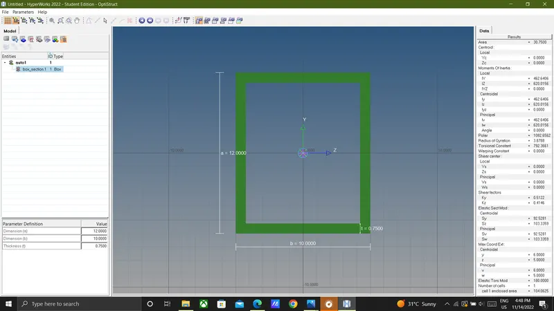
Cross-Section: BOX- Dimension a= 12 mm
dimension b=10 mm
Thickness t= 0.75 mm
b. Beam element:- All DOF should be constrained with RBE3 link
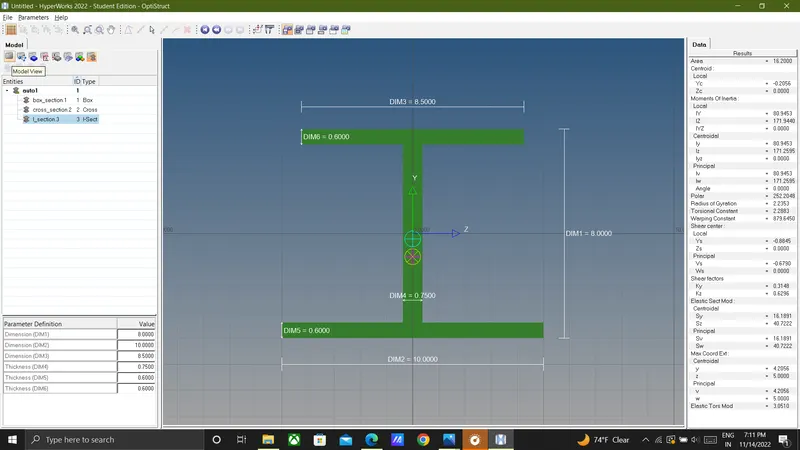
Cross-Section: I Section- Dimension a= 8 mm
Dimension b= 10 mm
Dimension c= 8.5 mm
Thickness t1= 0.75 mm
Thickness t2= .6 mm
Thickness t3= .6 mm
c. Bar element:- Constrain only x and y DOFs With RBE3 link
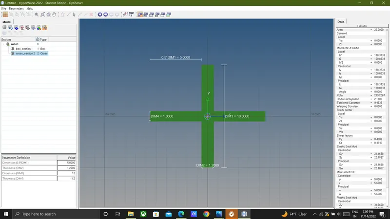
Cross-section: X section- Dimension DIM1= 5 mm
Thickness DIM2= 1.2 mm
Dimension DIM3= 10 mm
Thickness DIM4= 1.2mm
d. & e. Apply the mass of magnitude 10 with the RBE2 link
f. Join the two components with Spring elements.
CAD Model:
Procedure:-
1) IMPORT THE MODEL:-
- Open the Hyper mesh software.import the model by selecting (Import<geometry<IGES)
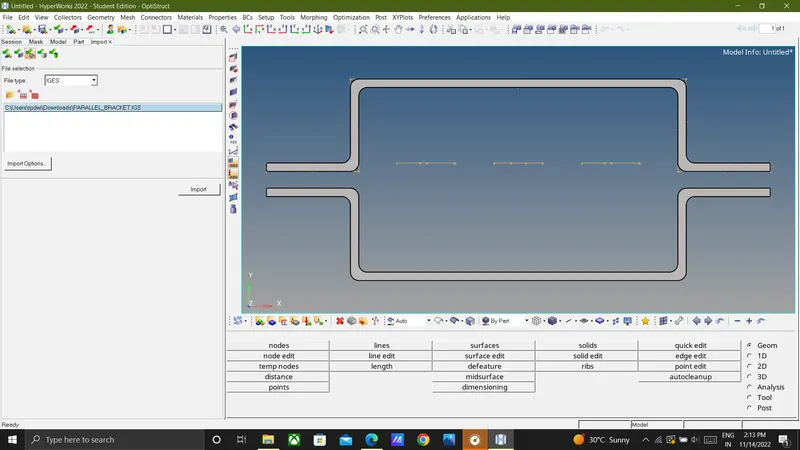
2) EXTRACT MIDSURAFCE:- In main menu page selected the Geometry option , then slected the midsurface tool.
(Main menu> Geomtery > midsurface > select the surface/All>automidsurface >extract)
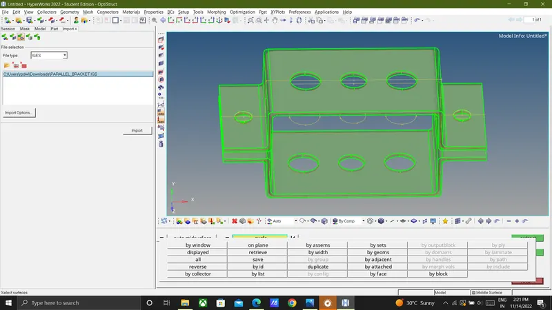
change the color Both bracket.
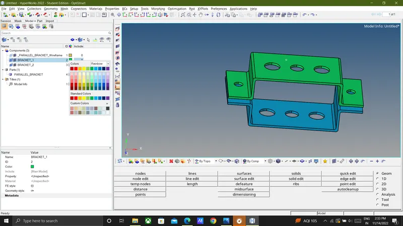
then deleted the solids by (Delete>select solid > delete entity) .
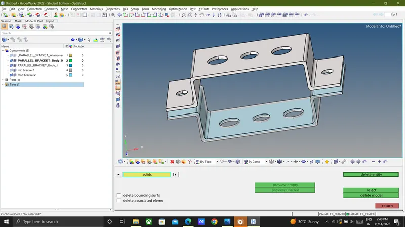
and also deleted the bracket solids in model tress > componenet > selected the two solid body of an bracket.
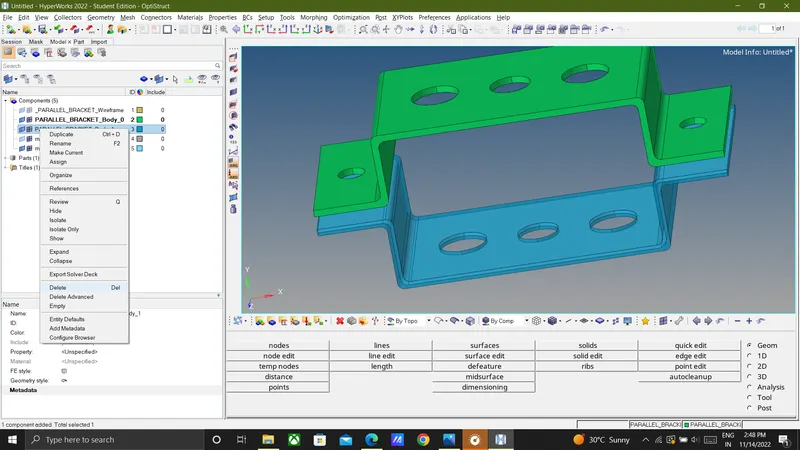
3) ASSIGNING MATERIALS AND PROPERTIES TO THE MIDSURFACE:-
In model tree do right click to create material named as steel.
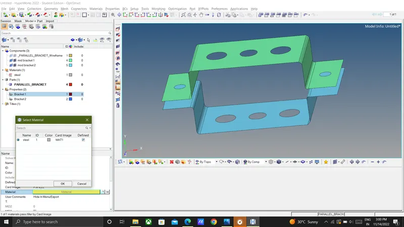
Then created two new properties for 2 parallel brackets in model tree.because it has 2 different thickness.
Created properties of the bracket_1 & bracket_2
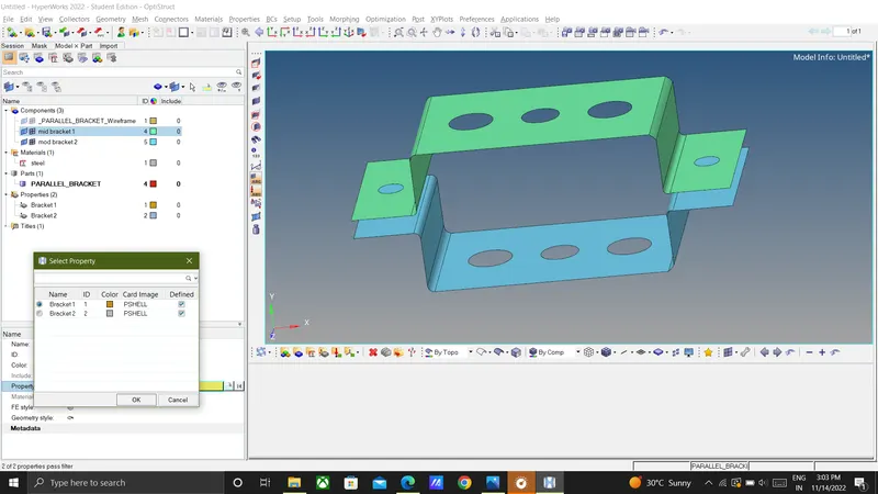
Now do to assigning newly created properties to the midsurface.
Set the thickness value of the bracket_1 = 2.5 mm and card image as PSHELL in bracket_1 property in model tree.
Same as set set the thickness value of the bracket_2 = 2 mm and card image as PSHELL in bracket_2 property.
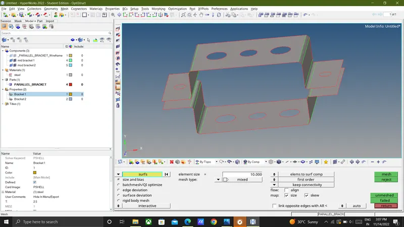
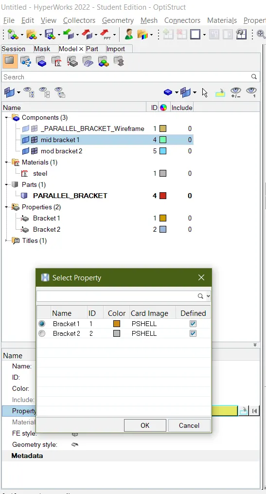
Then go to the componenets in model selected the bracket-1 component to set the assigned the bracket -1 property.Same as selected the bracket-2 component to set the assigned the bracket -2 property.
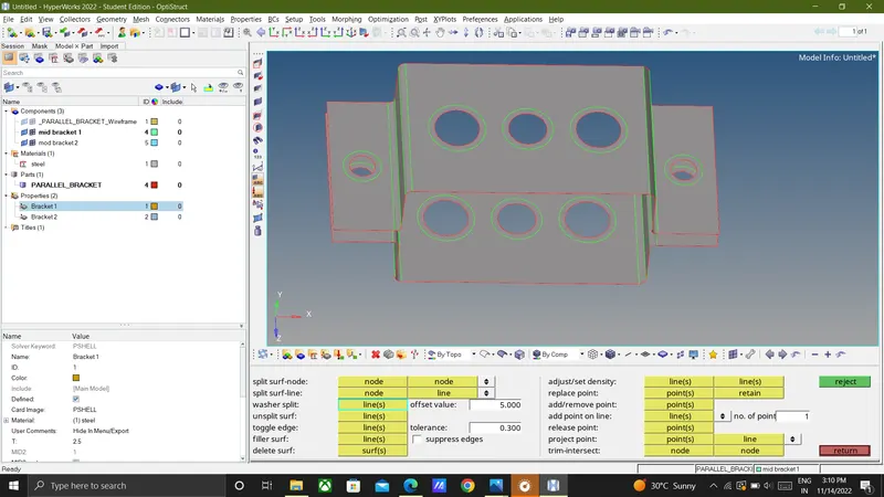
Go to quick edit and give washersplit of 5mm offset at all holes.
5) AUTOMESHING:-
use 2D automesh and selct the element size as 5 units and mesh type as mixed type.now,first select the washer zone and mesh.(2D mesh>automesh>Select Surface>mesh size>mesh)
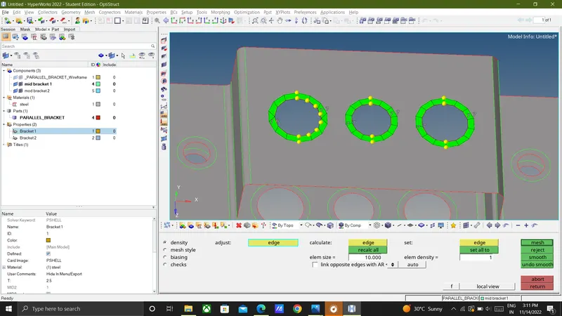
To attain a proper mesh flow we can just increase or decrease the nodes by using mouse button operation.
mesh the remaining ares and achieve proper mesh flow (2D mesh>automesh>surfs>Select Surface/All>mesh size>mesh)
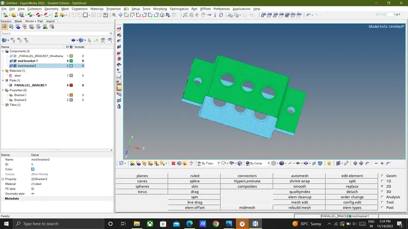
6) 1D ELEMENT CREATION IN THE FE :-
Create rbe2 link at a,rbe3 link at b,rbe3 link at c,rbe2 link at d&e.
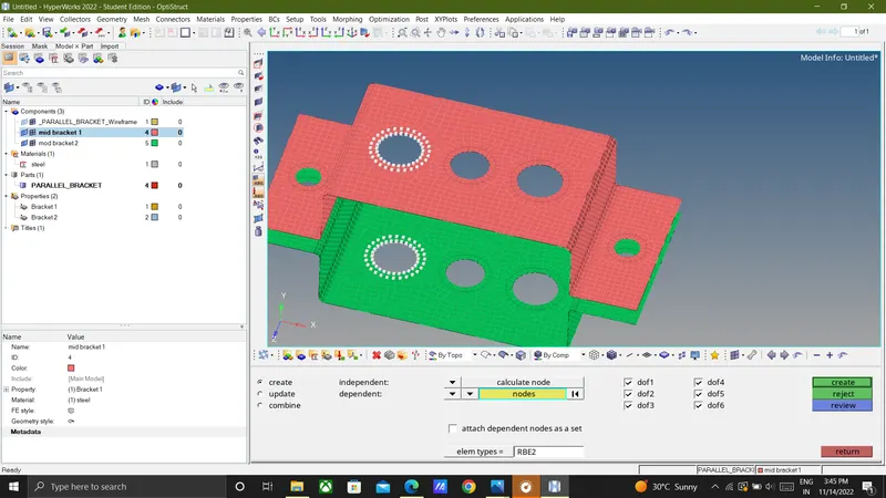
For RBE2 use command (1D>Rigids>multiple nodes>calculate node>select the nodes>provide DOFs>create)
For RBE3 use command (1D>RBE3>Calculate node>Element type-RBE3>create)
for mass command (1D>Mass>select node>element type>camms1>create)
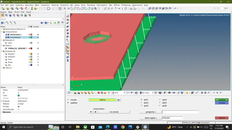
For spring use command (1D>Spring>Select node>element type>celas1>Create)
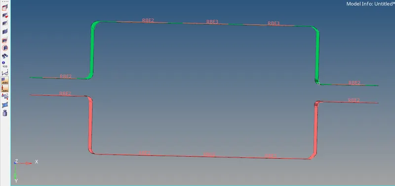
Rod element.Beam element & Bar element-
To create 1D elements for the washer area according to the given parameters and to create hyperbeam elements like rod,beam,bar we should first cretae a hyperbeam according to the given parameters at the top.The rigids can be created by using multiple nodes option and nodes can be created by path.(1D>Rigids>select the nodes>by path> create)
Step1:
- To diploy Rigid connection for the washer elements for the parallel bracket.
(1D>Rigids>multiple nodes>calculate node>select the nodes>provide DOFs>create)
for,the washer area' a' to diploy RB2 connection these are the DOFs to be considered :
1.Transulation-x[dof1].
2.Transulation-y[dof2].
3.Transulation-z[dof3]
To create Rod element between the parallel Brackets we should create a hyperbeam solid body according to the given dimensions.
The selected cross-section for Rod element is BOX(1D > Hyper beam > standard section > thinwalled box > create >Assign with given dimensions also renamed as Rod)
Now to create beam we have to follow some steps.
(1D > Hyper beam > standard section >standard I section > Create > Assigned with given dimensions and Renamed as a Beam)Assigned the cross section of the BEAM
Now to create Bar we have to follow some steps.
(1D > Hyper beam > > Standard Section library (OPTISTRUCT) > Standard section type (CROSS) > Created)
> Assigned with given dimensions and renamed as a BAR.
- Add properties of rod,bar,beam and assign cross sections to them.
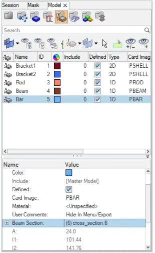
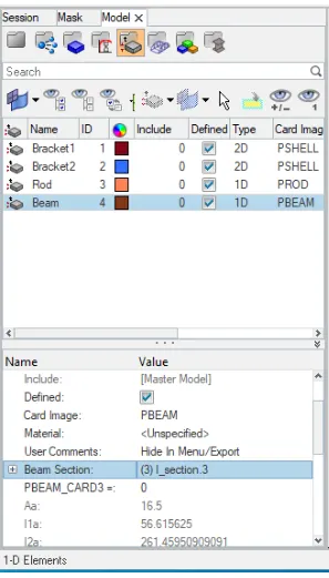
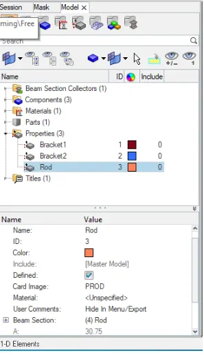
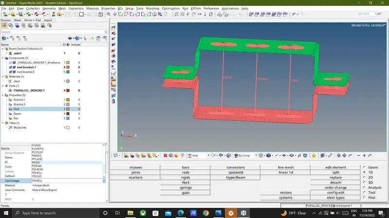
Go to rods select nodes,and assign property of rod,element type c rod same as beam and bar element.
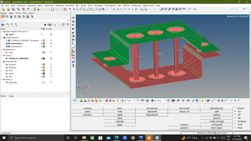
Turn on the 1D Traditional and detailed element representation to view the model as a solid part.
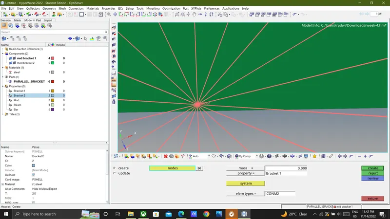
Go to (1D>masess<create<nodes< give mass value 10 and property of bracket2 and element type as cmass).
f is to join the two components with a spring elements : (1D>spring>select the nodes>create)
7) Result:
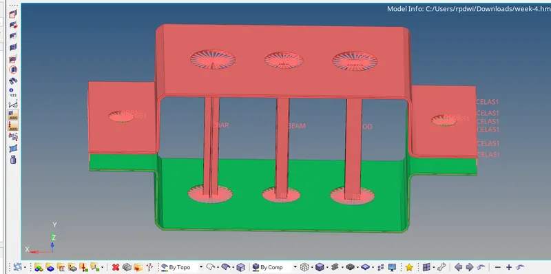
Mesh the Given component with the Size of 5 Units and Creating 1D elements on the following component with given cross-section and DOFs is done and shown below.
8) Learning outcome:
- ROD element as given dimension with RBE2 link created and Translational DOF constrained with RBE2 link successfully at A section
- BEAM element as given dimensionn with RBE3 link created and all DOF constrained with RBE3 link successfully at B section
- BAR element as given dimension with RBE2 link created and X and Y DOF constrained with RBE2 link successfully at C section
- Mass has been applied with magnitude of 10 successfully at D & E section.
- Joining the two components with spring elements created successfully at gap F