Week - 4 - 2D meshing for Plastic components
WeeK-4-2D MESHING FOR PLASTIC COMPONENT
Aim:
Performing Geometry Clean-up and remove any topological error, extracting mid-surface of every part,mesh with the given quality criteria and assign thickness,than draw model as solid.
Methodology:
The methodology for the given element is as follows:
- Import geometry and delete undefined property.
- Perform a Geometrical clean up
- Extraction of Mid surface
- Giving the Quality Criteria.
- Creating a mesh
- Draw shell as solid
Given Model:
The Model given is the Bottle Cap. The quality Criteria is as below
|
Sr No. |
Quality Criteria |
Value |
|
1 |
Target/Average length |
1 |
|
2 |
Minimum Length |
0.5 |
|
3 |
Maximum Length |
3 |
|
4 |
Aspect |
3 |
|
5 |
Warpage |
15 |
|
6 |
Skewness |
45 |
|
7 |
Jacobian |
0.7 |
|
8 |
Minimum Quad Angle |
45 |
|
9 |
Maximum Quad Angle |
135 |
|
10 |
Minimum Tria Angle |
30 |
|
11 |
Maximum Tria Angle |
120 |
|
12 |
Tria Percentage |
15 |
- Procedure.-
1) Import geometry and delete undefined property.
first of all model created by design engineer based on requrement but that engineer is not understand about this model is good or bed then ansa software required for the check the quality criteria.
First of all import a file of bottle caps_in ANSA softwere(ANSA V.22) OPEN>BOTTLE CAP MODEL>
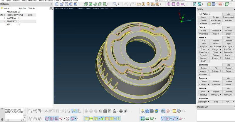
- Now go to the model browser by Tool Bar Menu >> Model Browser/Properties.
- To see how many components are availabale in the model.
- Here inly one component is available,Delete the unnecessary models in the model browser.
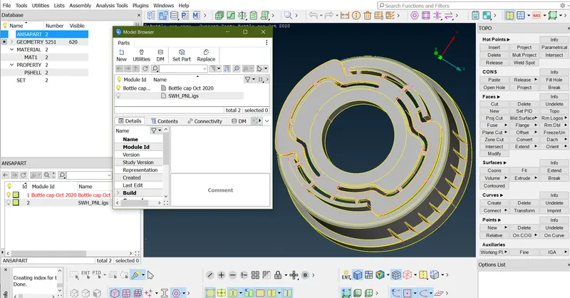
- Simillarly do the same thing in property browser also.
- If there are any unnecessary properties delete that and then proceed in next step.
after that change the perimeter length to 1 mm. this opction is available at MESH>PERIMETERS>LENGTH>
this change is required for better(fine) geometry.
2) Perform Geometry Clean Up-
- Here we will be doing some geometry checks on the parent component.
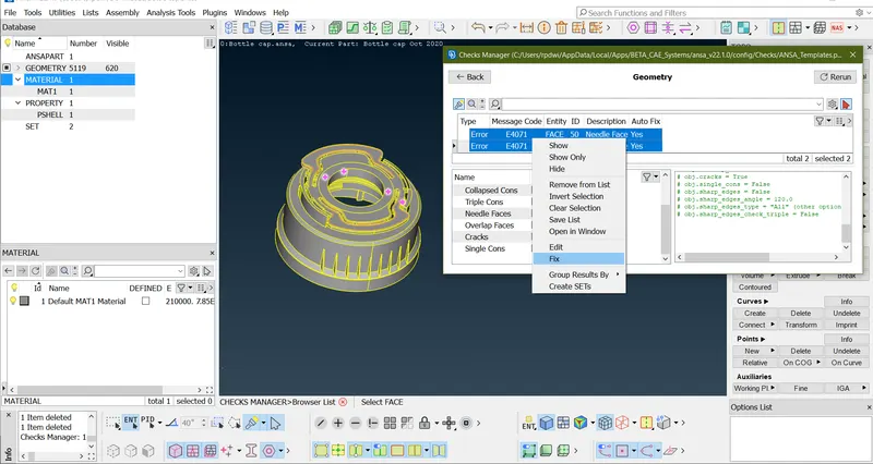
- To fix the geometry checks go to <Tool Bar >Checks>Geometry>
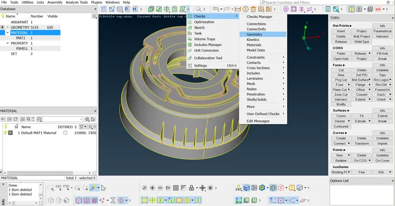
- We have to fix the geometrical errors in the parent component,Then only we will be able to extract midsurface.
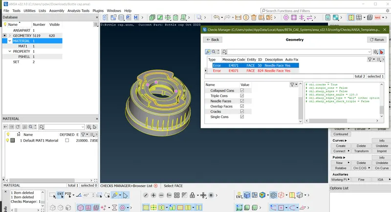
as above image two needle face error are present in perent geometry to fix it with select all error and give right click of mouse and than fix it by automatically.
3) Extraction of Mid surface-
- Before extracting the mid surface for the components we need to give perimeter and macros length on the components while extracting mid surface.
- This makes the component to get a desired shape,So it will be easy to extarct a midsurface without any errors.The possiblities of errors will be less.
- To give perimieters and macros length on the componets is 1, Mesh>Perimeters>Length>.
- Simillarly do the same thing for the macros also.
- Mesh>Perimeters>Length.
- Before extracting the mid surface for every component,We should measure the thickness of the component and then we have to proceed to extract the mid surface.
- If the component thickness is less than 6mm then we will come to know it is a sheet metal or plastic component.
- We can Extract Mid Surface by Two Methods called
- Using Skin MidSurface Option in Faces Panel in Topo Module.
- Using Offset Tool in Faces.
- But for this component,We will be extracting midsurface by using offset.
- We can extract midsurface for this component manually because this component is plastic.
- The plastic component will be having varying thickness,So extract midsurface manually.
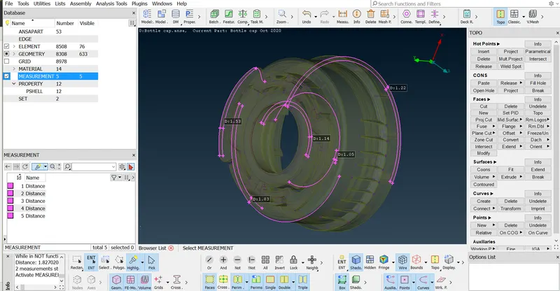
Before extraction or if you using mannual method of exteact mid surface know the thickness of the surface.
Some thickness of the surface as below-
Opner-1.53
center ring-1.14
middle ring-1.05
outer ring(Big)-1.22
bottom ring -.83
- Opner mid surface.-
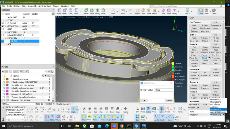
as above mensioned thickness of opner part (1.53) extracting mid surface follow the stage-FACES>OFFSET>SELECT FACE>
[Note:While extracting the midsurface,make sure to uncheck delete original faces option.and create PID automatic]
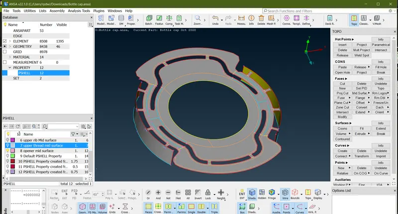
- Centre ring Mid Surface-Following Same operation as above generating mid surface.<FACES>OFFSET>SELECT FACE>
- Here we are extracting misurface for this inner circle.
- Before extracting midsurface for this inner circle.
- Hide that inner circle using not tool in focus tool bar.
- And then retrieve that inner circle using Invert tool in focus tool bar.
- Now extract the mid surface for that using OFFSET in the faces panel.
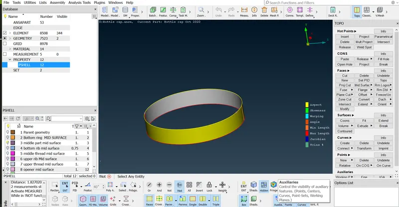
- middle ring Mid surface-Following Same operation as above generating mid surface.<FACES>OFFSET>SELECT FACE>
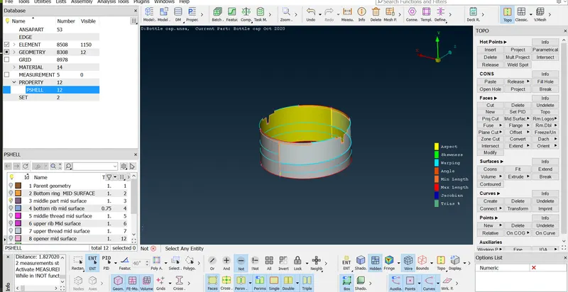
- middle part mid surface-Following Same operation as above generating mid surface.<FACES>OFFSET>SELECT FACE>
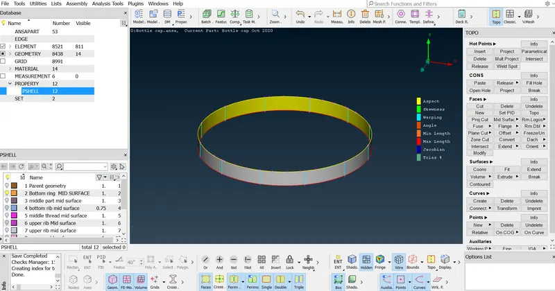
- Bottom ring mid surface-Following Same operation as above generating mid surface.<FACES>OFFSET>SELECT FACE>
- Extracting Midsurface for outer ribs-
- Here we can extract midsurface by three methods called
1) Creating a curves over the ribs and fill the surfcace.
2) Using middle single option to extract.
3) Using middle multi option to extract.
- Here I'm using method one to extract midsurface for outer ribs.
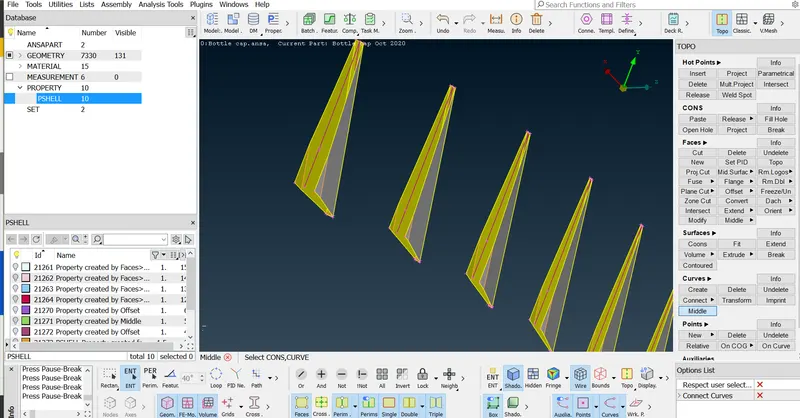
- First create a curves using middle option in curves panel.
- Go to <Topo Module >Curves>Middle>Select the appropriate surfaces >Middle Click.
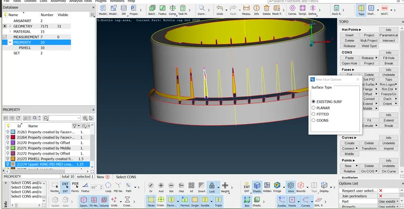
- as shown in below image is project this mid line into inner surface are and than create a new face.
- Now create a surface using new in faces tool.
- Go to Topo Module> Faces > New > Fitted > Create.
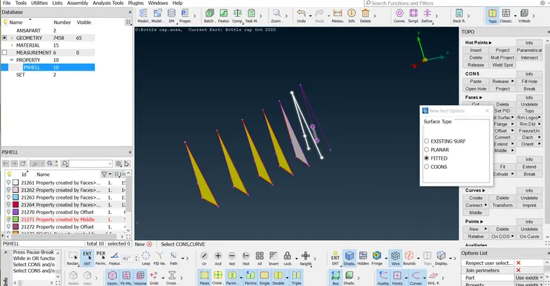
- After Creating the surface extend the surface to the mid surface extrcated for the outer circle.
- Simillarly do the same process for every rib and do the same thing for the inner ribs also.
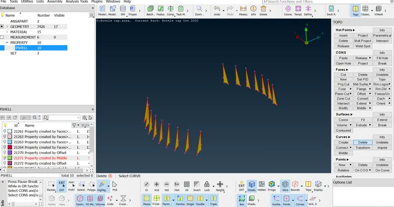
- when mid surface done extend this rib into the surface.<Tool>faces>Extand>select the con(convert cone into green line)>select the face >middle mouse click>.
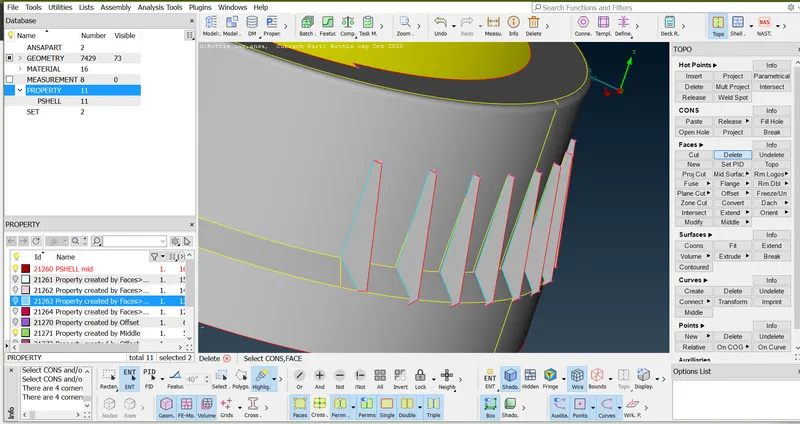
- Inner rib mid surface-
to generating mid surface of inner rib mid surface by using middle multi.
- Go to Topo Module> Faces > Middle > Multi > Select the appropriate surfaces> Middle Click.
- It is applied on selected or automatically identified groups of Faces.
- The resulting Faces can be automatically connected to the rest of the part.
- when mid surface done extend this rib into the surface.<Tool>faces>Extand>select the con(convert cone into green line)>select the face >middle mouse click>.
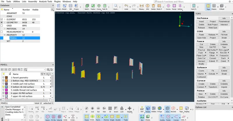
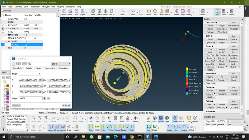
in here using smart work im not creating mid surface of every rib part also i can use transform option because it will take time is too less,where the ribs/teeth have multiple copies going around the component surface, we can make use of the <Transform > copy > rotate> option. Before doing that, we can extract the midsurface of one of the ribs/teeth as a precursor. After that,
kept in mind total no. of rib N=9-1=8 step's
Know the angle 360/9=40 degree.
we need to create an axis using two points at different heights. This is done using the <Tool>Points > On COG> tool. Using that, we just need to select two circular regions that share the same axis as the rotational plane of the ribs/teeth.
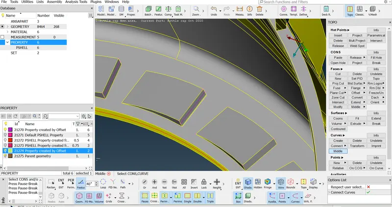
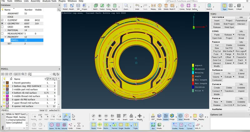
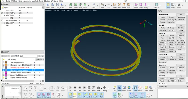
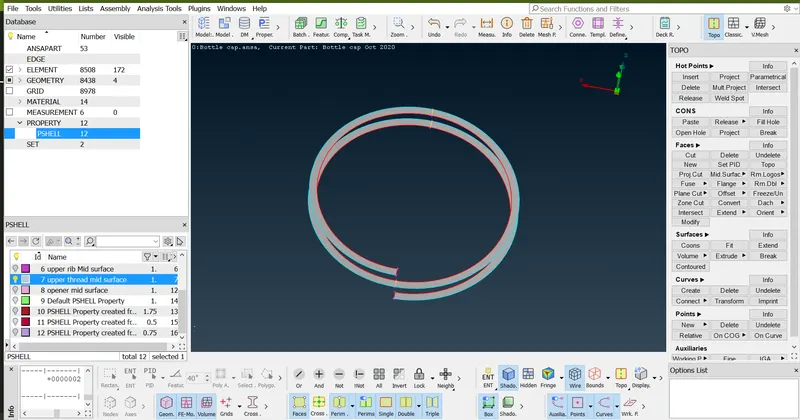
- Two inner thread mid surface-
- First create a curves using middle option in curves panel.
- Go to <Topo Module >Curves>Middle>Select the appropriate surfaces >Middle Click.
- as shown in below image is project this mid line into inner surface are and than create a new face.
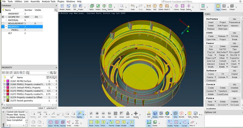
final mid surface of Cap model-
once generate mid surface and extand the rib and threadpart into a surface of all the prats it look like below images.
4) Giving the Quality Criteria-
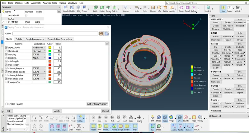
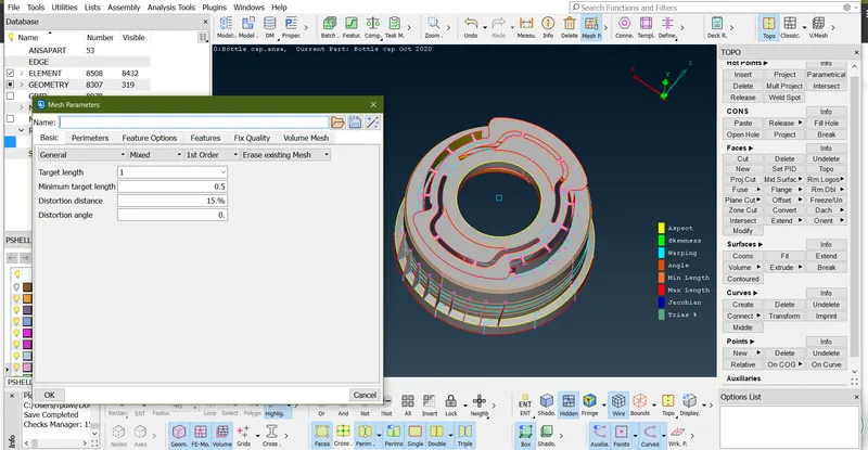
- Use the F11 key to open the Quality Criteria and Presentation Parameters management window (F11 Menu).
- Tool Bar >> Quality Criteria (F11) >> Enter the Values.
- Tool Bar >> Parameter >> Enter the Values.
Target/Average Length- 1 Unit
| Sl. No. | Quality Criteria | Function / Definition | Value |
| 1 | Aspect Ratio Ratio | Ratio of Max. Length by Min. Length | 3 |
| 2 | Skewness | Deviation from the ideal shape | 45 |
| 3 | Warping | Angle between the 2 planes of the same element(Quad) | 15 |
| 4 | Jacobian | Transformation of Coordinate System. | 0.7 |
| 5 | Min. Length | Shortest length of any given element | 0.5 |
| 6 | Max. Length | Longest length of any given element | 3 |
| 7 | Min angle Quad | Minimum angle in any given Quad element | 45 |
| 8 | Max angle Quad | Maximum angle in any given Quad element | 135 |
| 9 | Min angle Tria | Minimum angle in any given Tria element | 30 |
| 10 | Max angle Tria | Maximum angle in any given Tria element | 120 |
| 11 | Tria % | Percentage of Tria on any meshed surface | 15 |
5) Creating a mesh-
- To begin mesh,Switch form topo module to the mesh module.
- Before Meshing set the perimeter and macro length to the component.
- Here set the perimeter and macro length as target element size.
- It will split according to the target element size,So it will be easy for us to mesh.
- To Mesh >> Go to Mesh Module >> Mesh Generation >> Best Mesh >> Select the area.
- While Meshing Switch from shaded mode to the hidden mode,Then only we will be able to see the visibility element quality.

Conditions to be followed while meshing
- Feature Capturing
- Feature capturing is must while meshing.All the nodes must be connected to the shared edges.
- Tria Management
- Avoig higher number of trias.
- OFF Element-
No off elemrnt in the model
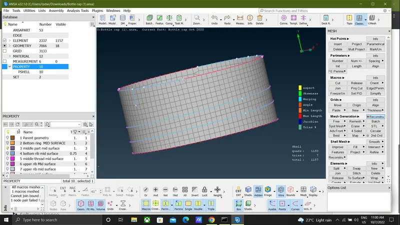
middle part mesh- Using tool of messhing is-><Classic mesh>mesh generation>best>select the faces> middle mouse click.>
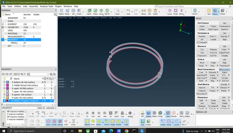
- thread's mesh-
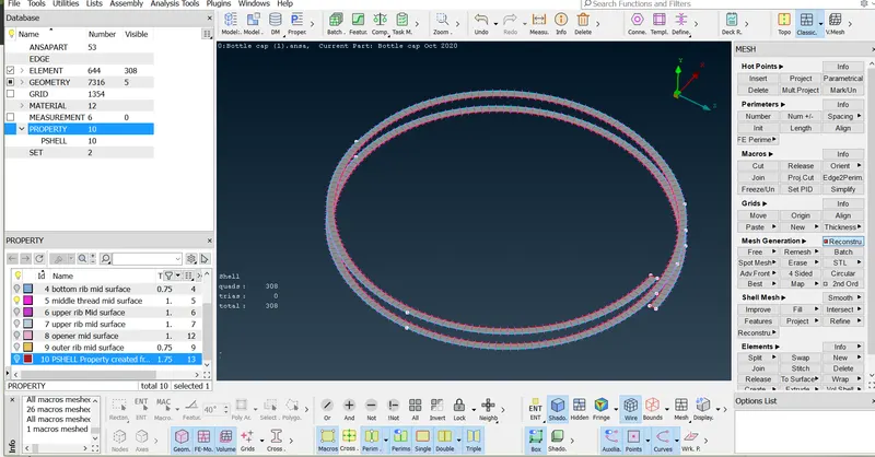
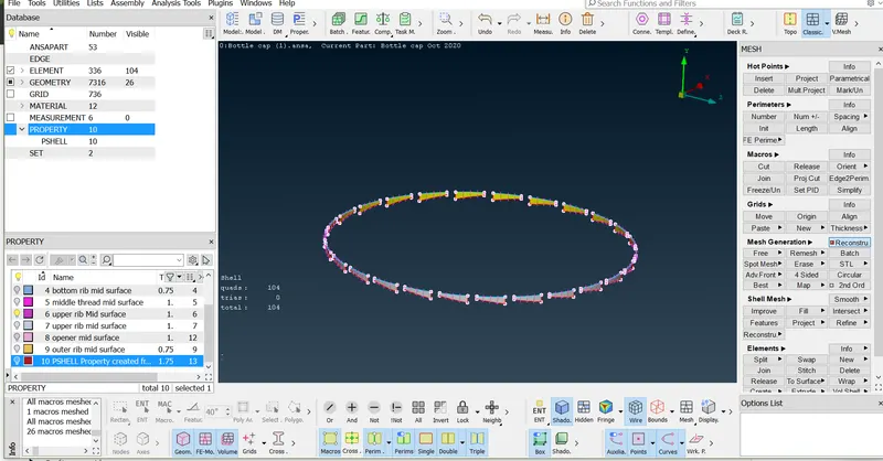
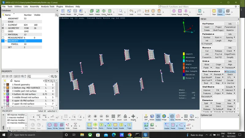
lower rib mesh-
Botoom Ring mesh-
as below image to avoide quality faliour first create a cut by using <TOOL>FACES>CUT>SELECT THE CONE>CLICK MIDDLE MOUSE CLICK.>
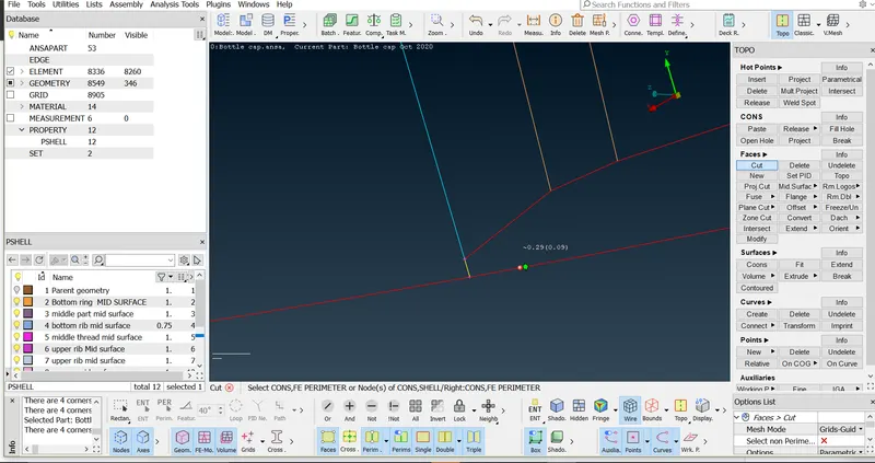
after cut operation create new faces hear by using<Tool>faces>new<select the con>coons>ok>
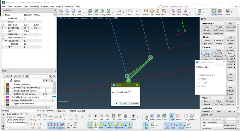
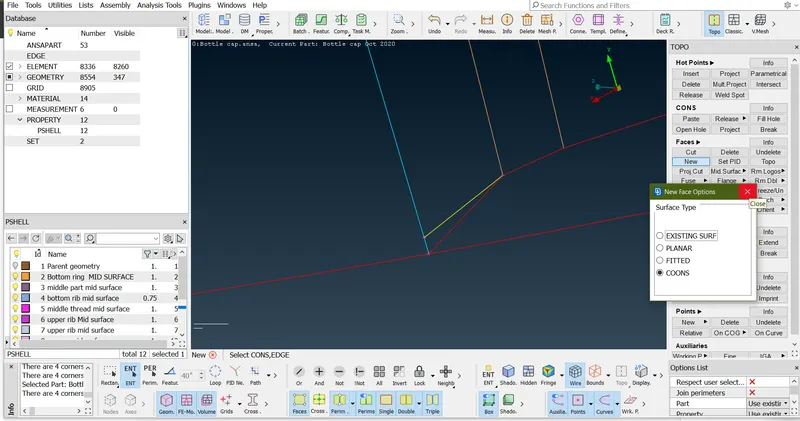
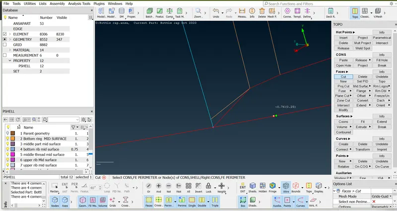
when face is generated tongle the yellow line or cut it buy using <Tool>faces>cut>right click in the yellow line>
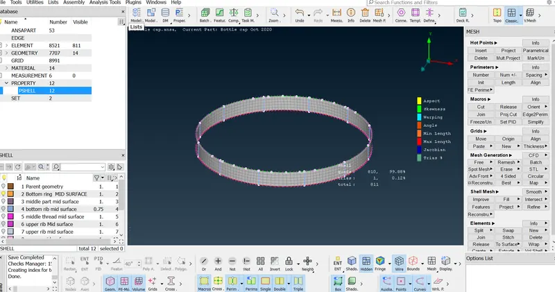
Go to mesh by using <Clasic Mesh>mesh generation>best>select the face> give middle click of the mouse>
For good mesh quality divide the domain into appropriate sections by using
(CUT / JOIN COMMAND)
(MESH>GRID>PASTE) IF THE TRIA BACKWARD DIRECTION USE PASTE OPTION.
To apply mesh use (MESH< MESH GENERATION>BEST MESH> SELECT THE FACE) and to remove the mesh use
(MESH>MESH GENERATION>ERASE)
Clear the mesh quality by the combination of
(MESH>SHELL MESH>RECONSTRUCT/SMOOTH) (for automatic alternate mesh
suggestions / pattern smoothing effect ).
(MESH>ELEMENT>SPLIT/SWAP/JOIN) (toremove the trias and manipulate them)
(MESH>MACROS>CUT/JOIN/EDGE2PERIMETER)(Defining the region
to mesh )
- (MESH>PERIMETER>num+/-){LEFT CLICK TO INCREASE NO.OF NODES AND RIGHT CLICK OF MOUSE DECREASE NO.OF NODES.)
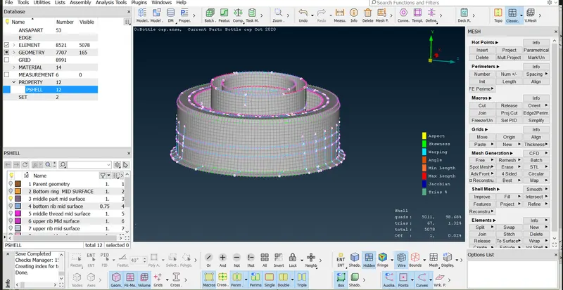
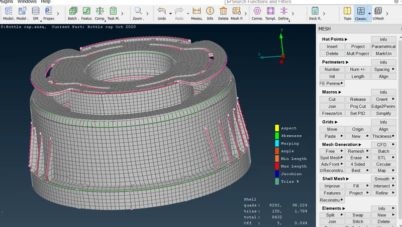
FINAL MESH MODEL-
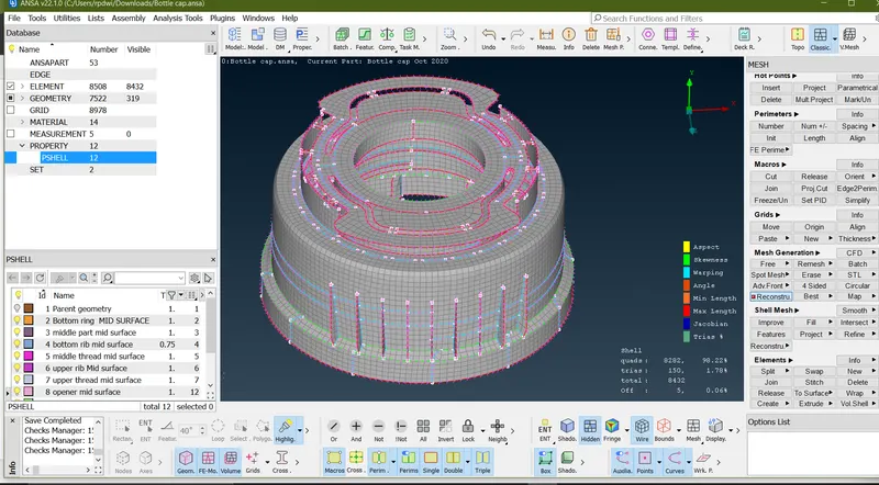
OFF ELEMENT-
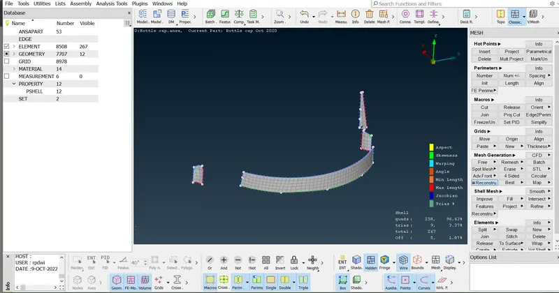
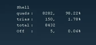
- 5 Trias are touching each other,We cannot drag them in the chamfer regions.
- Every trias are touching each other in the chamfer region.
- This is because of triple points in the chamfer region.
- If we try to eliminate that trias in the chamfer regions,The elements will be failing for jacobian,warping,So accept that trais and proceed.
- [NOTE-Here in this chamfer regions,elements will be failing for the minimum length,So we can't do anything here,So accept it and proceed. but try to remove as many off element as you can]
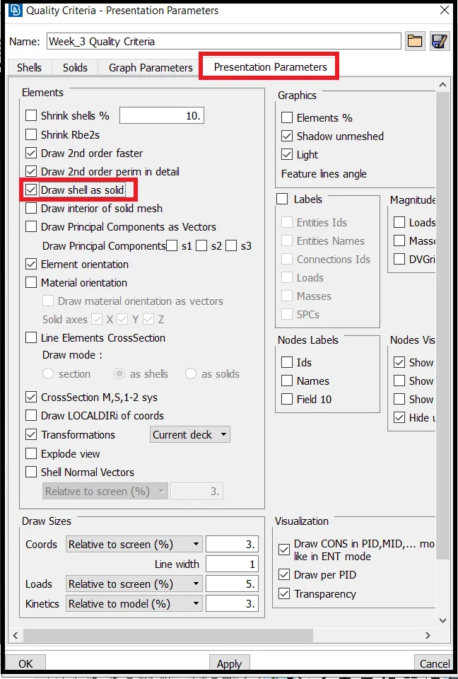
6) Draw shell as solid-
- To check Go to Utilities >Quality Criteria >Presentation Parameters >Draw Shell as Solid.
LEARNING OUTCOMES
1. Learnt to make use of the middle tool - a third alternative to midsurface creation.
2. Also learnt the transform > rotate option, to form copies of the same surface around an axis.
3. Was able to familiarize with the intersect, extend and project tools which were required for this component.
4. Also learnt to make use of curves to generate surfaces, be it through manually created curves as well as curves generated with the help of cons.
RESULT
The given bottle cap component was meshed as per required quality criteria, after having carried out topology cleanup and generated midsurfaces for each of its surfaces and thickness was assigned to each of them.
- A good mesh flow have been achieved with the 15 elements failing for quality
- Hence tria percentage with 1.78 % have been achieved.