Week 3 - 2D meshing for sheet metal
Week 3 - 2D meshing for sheet metal
AIM: for given hood model , take out mid surfaces for all the components in the model,
mesh these midsurfaces for all the component with given quality criteria ,and assign the thickness
GIVEN DATA:
Here given data provide are
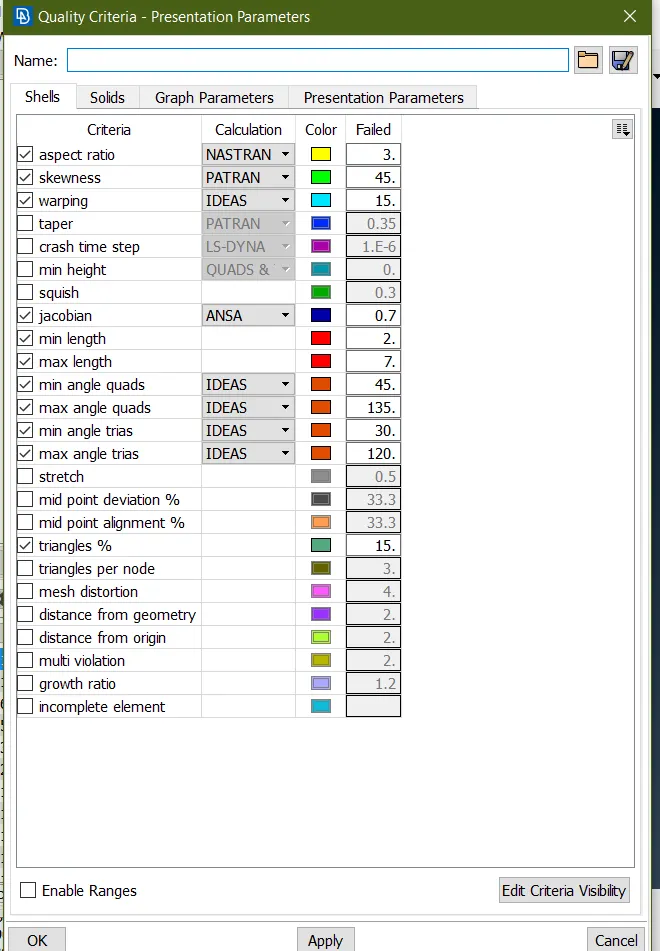
1.Quality criteria -
The quality criteria provided is mention below in the table-
|
S. NO |
Quality Criteria |
Value |
|
1 |
Target / Average length |
5 |
|
2 |
Minimum Length |
2 |
|
3 |
Maximum Length |
7 |
|
4 |
Aspect |
3 |
|
5 |
Warpage |
15 |
|
6 |
Skewness |
45 |
|
7 |
Jacobian |
0.7 |
|
8 |
Min Quad Angle |
45 |
|
9 |
Max Quad Angle |
135 |
|
10 |
Min Tria Angle |
30 |
|
11 |
Max Tria Angle |
120 |
|
12 |
Tria % |
15 |
2.CAD Model -
Using ANSA sowftwere V22.1.0.
To import car hood model in ANSA folloeing step's-
(FILE>OPEN>DOWNLOAD>OPEN CAR HOOD MODEL)
After import the model provided CAD model of car hood consisting of five components given below-
1)Latch
2)Right hinge
3)Left hinge
4)Inner pannel
5)Outer pannel
Once recognized the model some steps are followed of given model-
1)To check all the geometry error and rectify them
2)To check the thickness of all the components in the model
3)To extract the mid surface from the geometry
4)To generate mesh with good flow in the given quality criteria
5)After completing thr mesh draw a solid of all 5 component's.
PROCEDURE :
1) Check The Geometry:
After importing the model or Gemetry there will be some topological error's to firt rectifiy them.
To do a geometry clen-up it is an oimportant stage's-
(TOOL>CHECK MANAGER>GEOMETRY)
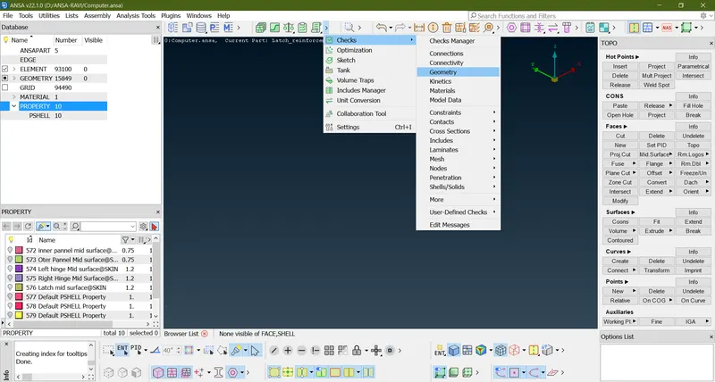
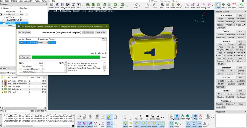
Follow same stage for every 5 Component's-
Latch Part-
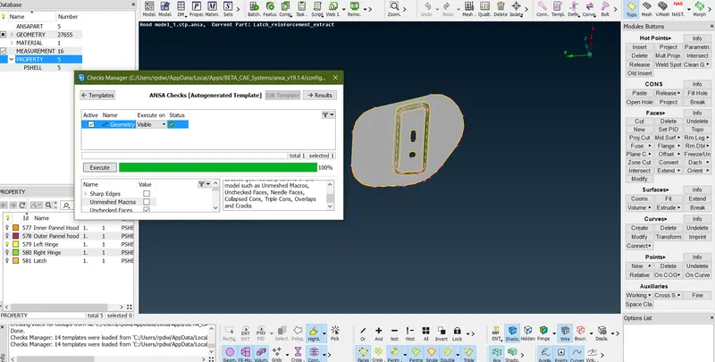
Left Hingh Part-
Right Hinge Part-
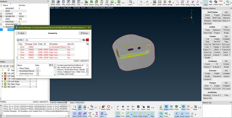
As shown in above part right hinge here it was 5 error present.
you have two method to fix this error either go mannual or go auto fix method.
Manual Method- First Go (check manager> check geometry> Execute)
In Above image here 5 error go triple cone and right click of mouse new option pop-up where click show only so in this operation wher this error persent that area highlighted than remove manualy this are and using topo.
Auto Fix Method-First G0(check manager> check geometry> Execute)
In This method Select all error's in Ctrl+A Or click left click of mouse and Drag mouse upword & downword direction and than a right click of mouse and than choose FIX option.
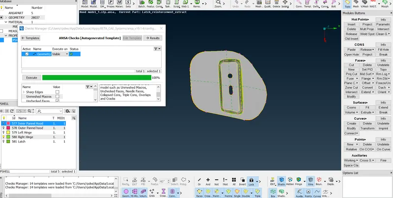
As you see above no error found in Right Hinge using fix option.
Inner panel part-
Outer Panel Part-
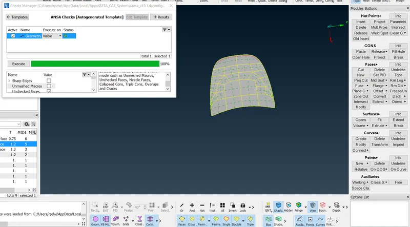
2) Check thickness of each component-
(Utilities>Messure>select the cons)
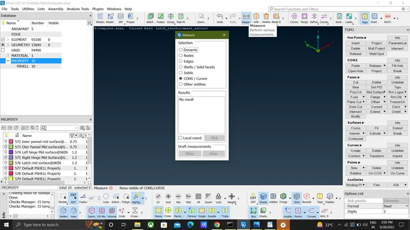
Here we have to check the thisckness of inner part of the model- messure the thickness with help messure tool
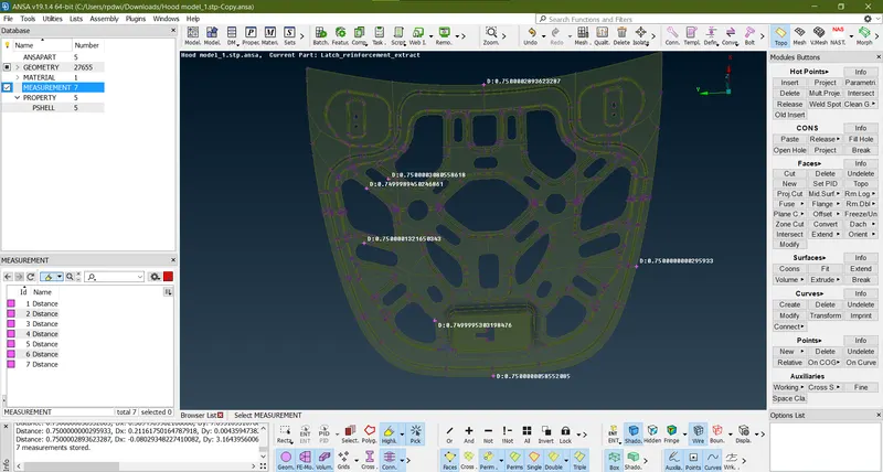
As above image of inner panel thickness is 0.75
similarily check thickness of all component are as follow's-
- Latch =1.2
- L hinge =1.2
- R hinge =1.2
- Outer panel =0.75
- Inner panel =0.75
3) MIDSURFACING-
There are two methods by which mid surfaces can be extraction-
1. Auto mid.(TOOL>FACES>MID SURFACE >SKIN)
2 . Manual method.(TOOL>FACES>OFFSET>FACE)
if the geometry is in closed volume where you can use auto mid extraction but if the component is not is in closed volume where you can use manual method.
As you show below image's create mid surface extraction by using of Auto mid Option with geometry check's.
Latch part-
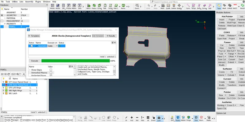
Lift hinge-
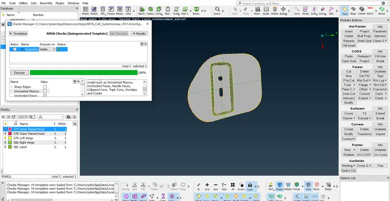
Right Hinge-
Inner panel-
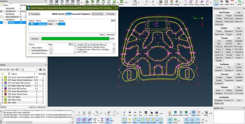
Outer Panel-
Once mid surface is generated of all the part we need to create a new PID of all 5 part's.
<TOOL>FACES>SET PID>CREATE NEW PSHELL>OK.
And check the geometry again,No error found in my model so go to next step-
4) Sizing Perimeter, Defeaturing & Mesh Preparations :
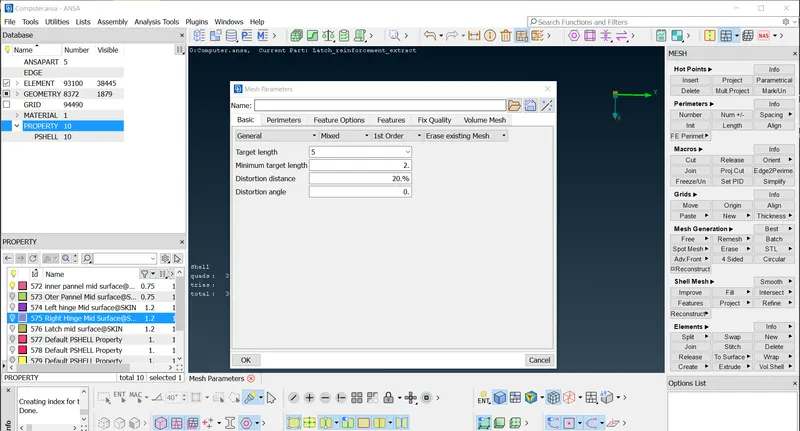
Now go to the mesh and select length option and put traget lenght as 5.
(MESH MODULE>PERIMETER>LENGTH)
Every time to excute any program we need to middle click of the mouse.
Before going for meshing do some other operation like as follow-
- Confirm whether perimeter element distances are in acceptable range
-
Remove unnecessary Hot Point's and again resizing perimeter elements distance
we can bring distance to acceptable range.
- Make sure hole edges are parallel to adjacent edges also Make sure that every hole's perimeter is even.
- if in part's having two constuction line distance is less than minium length(2mm)or region is too small on that region defeatuuring it.
Defeatureing-Compromise on any one feature to save another feature.
If you not doing this operation it might fail in minimum length criteria.
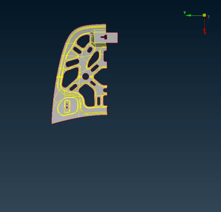
here in inner pannel geometry is bit complex so we check for symmetricity for that we use
(topo>face>Rm Dbl>Geometry>Symmetry plan>ok)
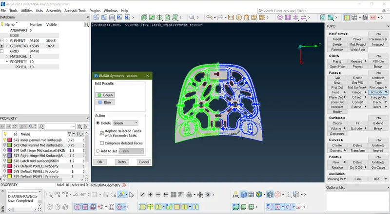
Doing this operation reduce much time and efforts.The blue and green colour indicate symmetrical portion in the selected component.after identifying delete half of the portion of symetry.
5) Defining Quality Criteria & Meshing Parameters-
6)Meshing-
For good mesh quality divide the domain into appropriate sections by using
(CUT / JOIN COMMAND)
(MESH>GRID>PASTE) IF THE TRIA BACKWARD DIRECTION USE PASTE OPTION.
To apply mesh use (MESH< MESH GENERATION>BEST MESH> SELECT THE FACE) and to remove the mesh use
(MESH>MESH GENERATION>ERASE)
Clear the mesh quality by the combination of
(MESH>SHELL MESH>RECONSTRUCT/SMOOTH) (for automatic alternate mesh
suggestions / pattern smoothing effect ).
(MESH>ELEMENT>SPLIT/SWAP/JOIN) (toremove the trias and manipulate them)
(MESH>MACROS>CUT/JOIN/EDGE2PERIMETER)(Defining the region
to mesh )
(MESH>PERIMETER>num+/-){LEFT CLICK TO INCREASE NO.OF NODES AND RIGHT CLICK OF MOUSE DECREASE NO.OF NODES.)
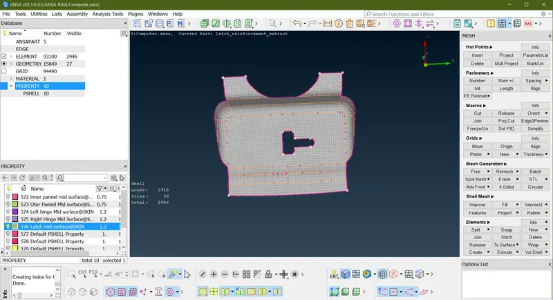
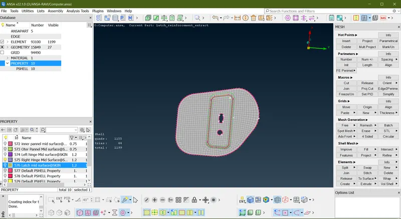
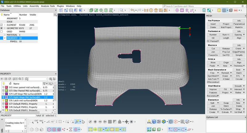
LATCH PART MESH-
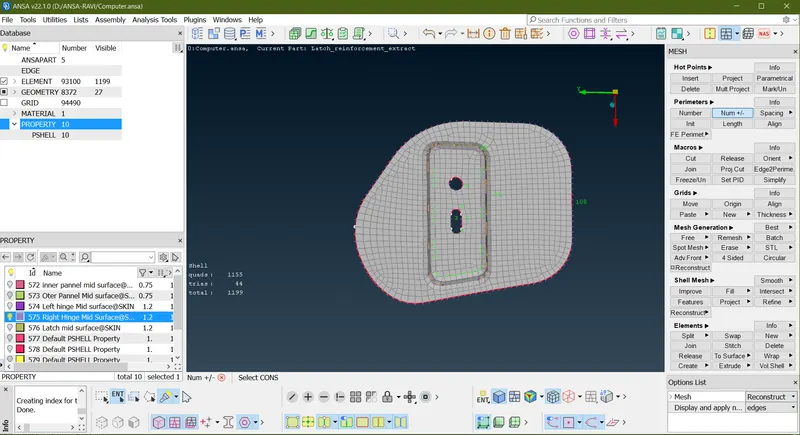
RIGHT HINGE MESH-
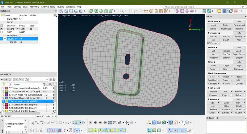
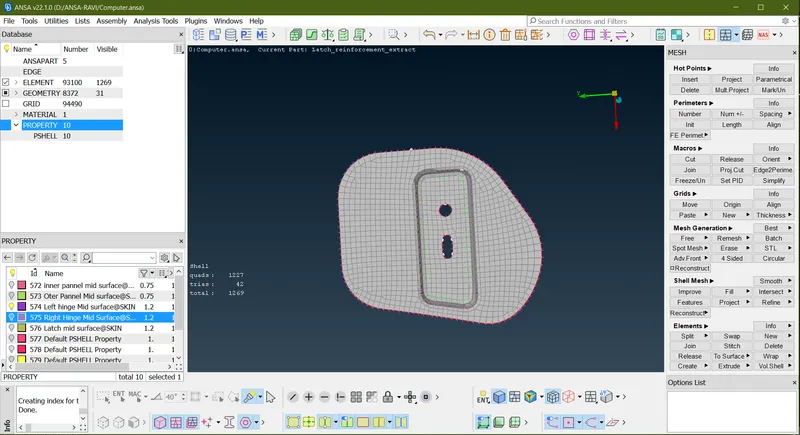
LEFT HINGE MESH-
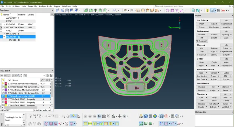
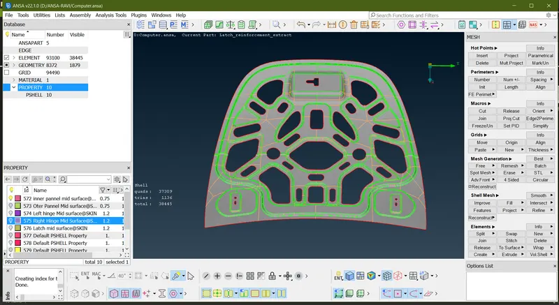
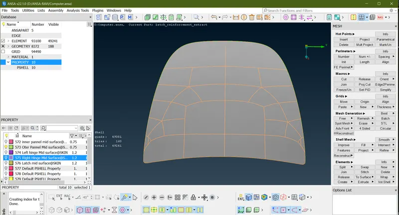
INNER PANEL MESH-
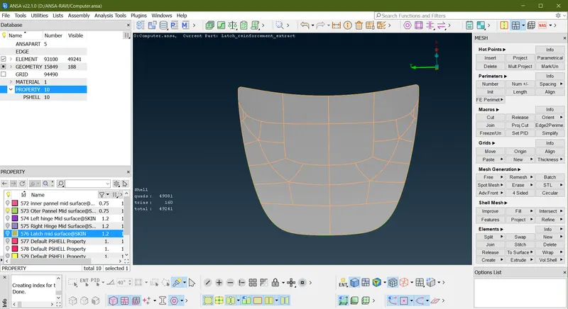
OUTER PANEL MESH-
7)DRAW AS SOLID-
in this command help us to identify whether the thicknessassignedto the mid surface is matching with the perent geometry or not because it help's to can visualize the 2D shell element to 3d shell element.
All component convert into solid help of below option.-
Go to (QUALITI CRITERIA/F11>PRESENTATION PARAMETERS>DRAW SHELL AS SOLID>OK)
1)latch.
2)R.Hinge.-
3)L.Hinge.-
4)Inner pannel.-
5)Outer panel.-
Learning outcomes-
- At the end of this challenge , i can able to
- Perform geometry clean up for any complex sheet metal components
- Generate midsurface / skin for any complex sheet metal components.
- Generate the shell mesh meeting the given quality criteria for any complex sheet metal components
- Identify the quality failure and resolve the failure & improve the mesh quality
Conclusion-
Geometry clean up,generate mid surface, assign thickness,asign quality criteria and meshing succefull done.
Auto-mid surface takes less time to extract mid surface as campair to manual method.
Using improve and reconstruction option reduce tria and re-construct the cell's.
also using NUM+/- reduse tria and re-arange the cells.