Week 4-1D Element Creation Challenge
AIM:
Mesh the Given component with the Size of 5 Units. Create 1D elements on the following component with given cross-section and DOF.
1.. Rod element: - Translational DOF should be Constrained with RBE2 link
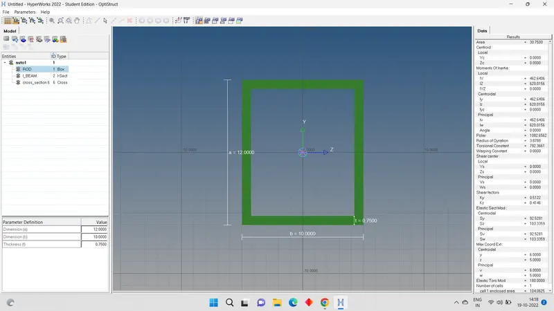
Cross-Section: BOX- Dimension a= 12 mm
dimension b=10 mm
Thickness t= 0.75 mm
- BEAM ELEMENT: - All DOF should be constrained with RBE3 link
Cross-Section: I Section- Dimension a= 8 mm
Dimension b= 10 mm
Dimension c= 8.5 mm
Thickness t1= 0.75 mm
Thickness t2= .6 mm
Thickness t3= .6 mm
- BAR ELEMENT: - Constrain only x and y DOFs With RBE3 link
Cross-section: X section- Dimension DIM1= 5 mm
Thickness DIM2= 1.2 mm
Dimension DIM3= 10 mm
Thickness DIM4= 1.2mm
- & e. Apply the mass of magnitude 10 with the RBE2 link
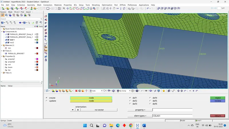
- Join the two components with Spring elements.
Procedure:
- Download the model and check the format of the model. It is in the format of .iges.
- Import the this cad model into the Hyper mesh by selecting the format of the IGES.
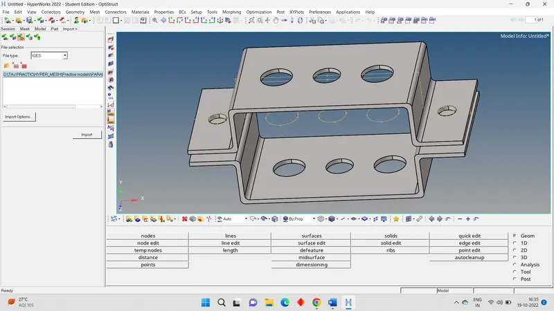
- Take the mid surface from the cad model. For that go to MAIN MANU TOOL > GEOM > MID-SURFACE > SELECT THE SURFACE > CREATE.
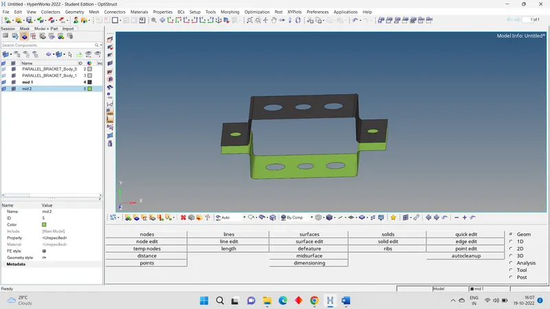
- Now hide the parent martial by going to model in left corner of GUI.
- Now, the mid created will automatically be shown in the same component of the part. We will be assigning new component for each of these mid-surfaces in order to assign proper thickness and materials later on. For doing the same we need to Right click on the component and select Create.
- The new components are named as MID1 & MID2. For moving the mid surfaces from the default component property to the new one we need to go to Tools>Organize then it will be showing to us the association of the given part with respective component.
- Once we make sure that the correct component is selected, we can then move the desired surfaces to the newly created components by collectors > surface > select > the > select the surface > move. Mid surfaces are now successfully moved to the new components.
- Now create the new martial for left click on the on left side of empty area. CREATE > MATERIAL Give the name.
- Also create the property of the in the same CREATE > PROPERTY. Now click on the property. In the left below we can information related to property. Here we have to change card image> PSHELL. And thickness > 5 mm. (we can also give the names)
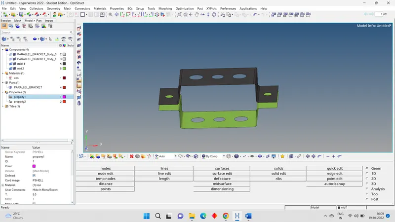
- Now we have to assign this property and material to the component or mid surface we created. For the we have to click the mid surface and assign the property.
- We have to create the washer around the hole in the mid surface of 5mm.
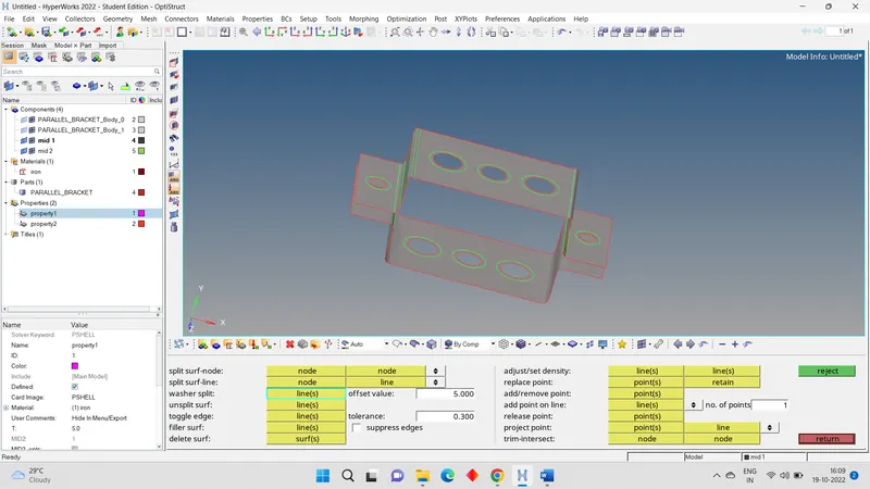
- Now we have to create the meshing for the mid surface. For that we have to go MAIN MANU TOOL > 2D > AUTO MESH > CHANGE THE ELEMENT SIZE AS 5 MM> SELECT THE SURFACE > MESH.
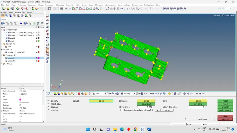
- We have make sure that number of node around the hole and washer should be same to avoid the trias.
CONNECTIONS:
- We have different types of 1D connection in the models are RBE2, RBE3, SPRING, HYPER BEAM (ROD of BOX cross section, I BEAM, X BAR).
- To create the hyper beam connections, we need the RBE2, REB3 connection.
- To create the RBE2 go to 1D > RIGID > CREATE > CHANGE THE DEPENDENT NODE AS MULTIPLE NODES& INDEPENDENT NODE AS CALCULATE NODE > SELECT THE DEPENDENT MULTIPLE NODE > CREATE.
(Note: we have to select the only dof1, dof2, dof3. Because it is constrained only translation dof is constrained)
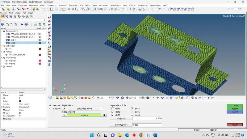
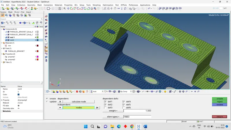
- In the same way create the RBE3. Consider one pair of rbe3 connection has all dof should be constrained. And another pair has constrained in X and Y directions.)
- Once the clusters are created, we can now create the ROD element by going to 1D > ROD > CREATE now select the master nodes of the clusters and assign the element type as CROD, keep the property tab blank as we need to create those properties in the Hyper beam with specified dimensions later on. Middle click will complete the operation and the nodes will be connected with a single line representing CROD.
- In the same create the BEAM and BAR
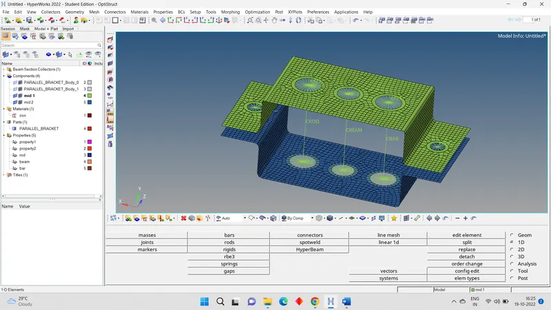
- For the holes d & e, we need to apply a mass of magnitude 10 units. Go to 1D>MASES, specify the mass as 10 keep the element type as default and select the master nodes of the resp. RBE2 Clusters and on middle click, the magnitude will be applied on the nodes.
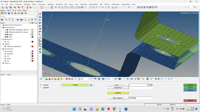
- For the spring element at areas f, go to 1D > SPRING > CREATE select the nodes on either end on the specified area one by one.
- To create the shape ROD, BEAM, BAR, we have to go for hyper beam section there we have to create the shape according to the dimension given the questions.
- Now we need to assign properties for these Rod, Beam and Bar elements. Right click under the model view anywhere in the blank space and create> property. Rename each of them as Rod, Beam & Bar.
- Now go to these properties one by one and assign them Card image, Material & Beam sections. For Rod choose Card image as PROD, Material as steel, Beam sections as we created in hyper beam . Same for Beam & Bar. Once we assign them here, we need to go to each element individually and update the properties in 1D section.
- Go to 1d >ROD >UPDATE > PROPERTYand select the property we just created. Same for Beam and bar component. For bar element we only need to constrain the X & Y Dof. Go to 1D >RIGID >UPDATE & select the resp. cluster then uncheck the dofs as mentioned and hit update.
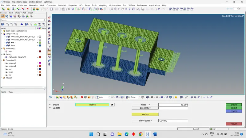
- After creating the shapes, we have to create the property according the shapes. Those properties we need to assign those connections.
- The final model shown below.
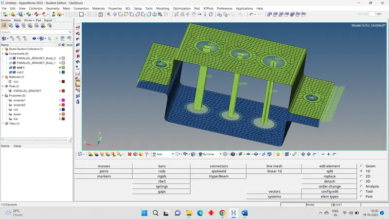
CONCLUSION:
This is challenge I have learned to how to make mid surface from the given component and meshing with specified mesh length. Also how to make 1D connections like RBE2 , RBE3 clusters. And how to connect the BAR, BEAM, ROD. How to assign the property to the hyper beams and connections.