Week 4-1D Element Creation Challenge
Objective:-
To Mesh the Given component with the Size of 5 Units. Create 1D elements on the following component with given cross-section and DOF
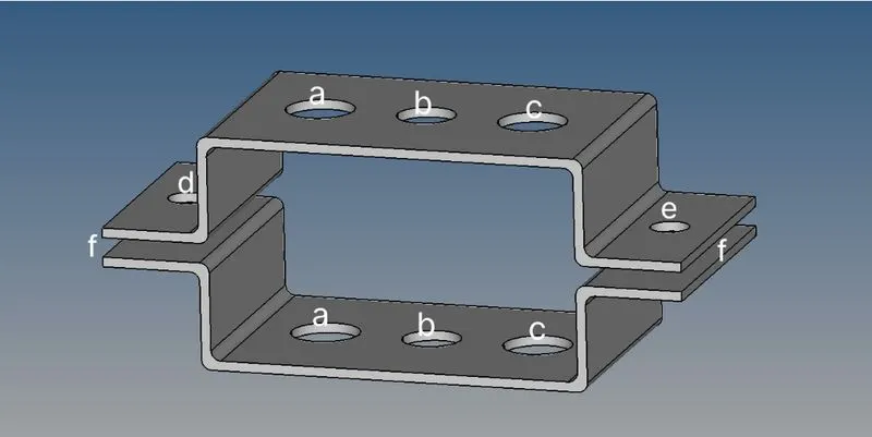
a. Rod element:- Translational DOF should be Constrained with RBE2 link
Cross-Section: BOX- Dimension a= 12 mm
dimension b=10 mm
Thickness t= 0.75 mm
b. Beam element:- All DOF should be constrained with RBE3 link
Cross-Section: I Section- Dimension a= 8 mm
Dimension b= 10 mm
Dimension c= 8.5 mm
Thickness t1= 0.75 mm
Thickness t2= .6 mm
Thickness t3= .6 mm
c. Bar element:- Constrain only x and y DOFs With RBE3 link
Cross-section: X section- Dimension DIM1= 5 mm
Thickness DIM2= 1.2 mm
Dimension DIM3= 10 mm
Thickness DIM4= 1.2mm
d. & e. Apply the mass of magnitude 10 with the RBE2 link
f. Join the two components with Spring elements
Procedure adopted:
challenge was started with creating midsurface from the solid geometry using Midsurface tool.After creating the midsurface, the generated surface was organised to two new components using organize tool. After that solid component is deleted.
Next step was to defeaturing the geometry with adding washer split option in quick edit tool.
Then mesh of size of 5 units were created using automesh tool.
after completing the mesh, 1D elements such as Rigid, RBE3 were created at the poits a,b,c as shown in the figure. For creation of the elements, nodes were selected using the option of "by path".
For creating spring elements in the geometry additional nodes were created using interpolate option in the node tool. spring element was created in those nodes with elemtype of HMSPRING.
Mass of 10 unit were added on the point d&e with RBE2 (rigid) element.
Before adding rod, beam and bar elements in a,b,c points property for each of these elements were created as shown in the figure.
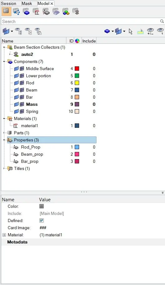
also using hyperbeam tool, required crossections were created and these crossections were assigned to the property. After completing the property creation, rod, beam and bar elements were created at points a,b&c. Then properties were assigned to the tod, beam and bar elements. As you can see in the above fig, each of these elements were created in seperate components.
RESULT
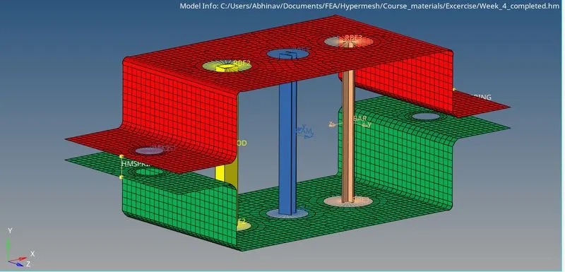
below fig shows the completed geometry in HM.