Week 4-1D Element Creation Challenge
Aim:-To mesh the given component and create 1D elements on the component with given cross section and DOF
Objectives:-create 1D elements on the component with given cross section and DOF
a)Rod element
b)Beam element
c)Bar element
Given component for the task is
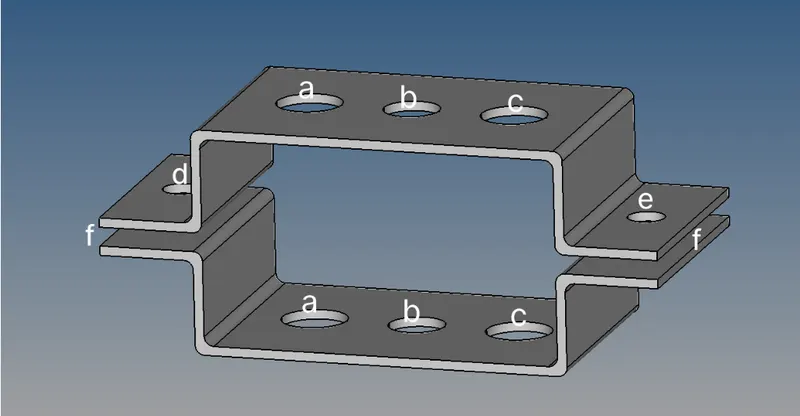
Elements cross section and DOF is given below:-
a)Rod element: Translational DOF constrained with RBE2 link
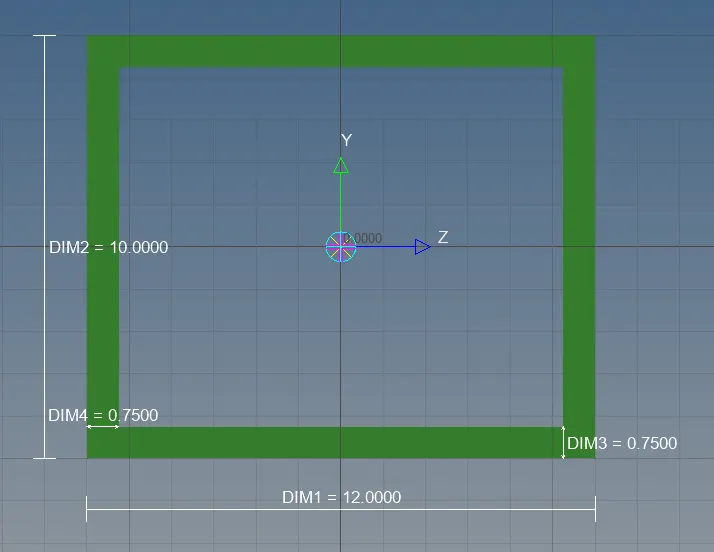
cross section:Box
Dimensions a=12mm
b=10mm
thickness=0.75mm
b)Beam element: All DOF should be constrained with RBE3 link
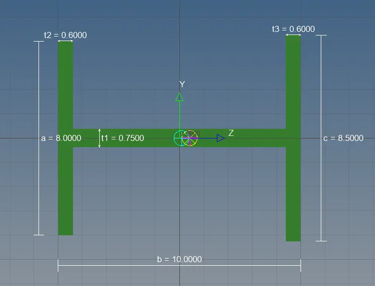
Cross section:I section
Dimensions a=8mm
b=10mm
c=8.5mm
thickness(t) t1=0.75mm
t2=0.6mm
t3=0.6mm
c)Bar element: only x and y DOF's should be constrained
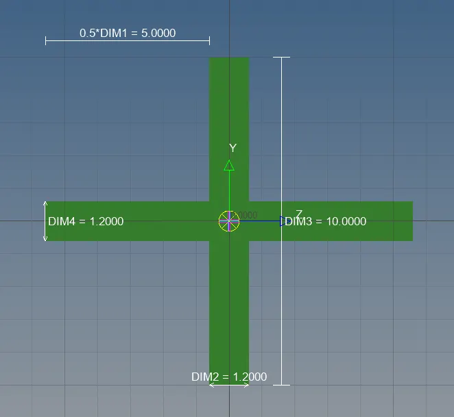
cross section:X section
Dimensions D1=5mm
D2=10mm
Thickness T1=1.2mm
T2=1.2mm
D&E apply the mass of magnitude 10 with RBE2 link
F join the two components with spring elements
Procedure:-
1.Import the model by selecting import solver deck>import geometry>File type:iges>click import.hence the model will be imported
2.The model will be in wire frame view,get that to shaded view
3.Extracing the mid surface
-geometry>midsurface>surfs>extract the upper bracket
-Extracted surface will be named as middle surface ,rename it into bracket1 and give a color for it
- geometry>midsurface>surfs>extract the lower bracket
-Rename the extracted surface as bracket2 and give a color for it
4.Hence the middle surface has been extracted
-create>material>steel
-create>properties>rename as bracket and assign steel as material
5.Assign the corresponding properties to bracket1 & bracket2
6.Delete>solids>all>delete entity
7.Add a split washer to the holes with a offset of 5mm so that there will be less stress concentration near the holes
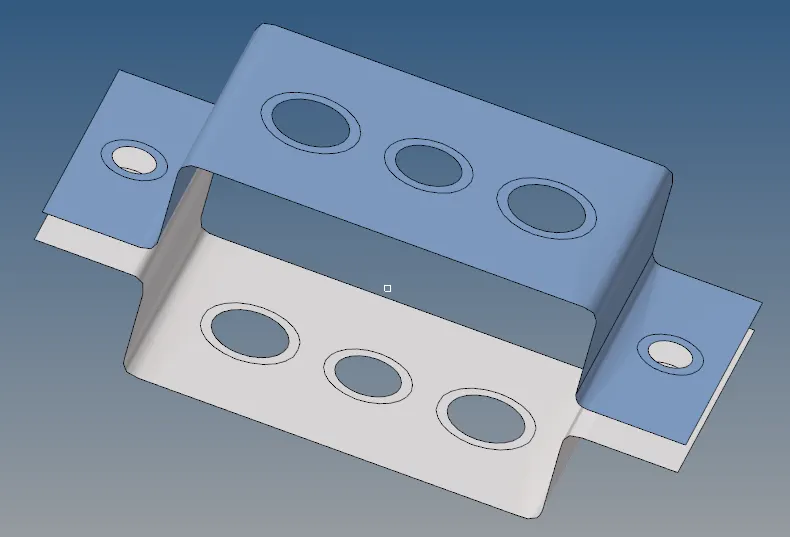
8.Now 2D>automesh>element size=5>surfs>all>mesh.Hence the model will be meshed
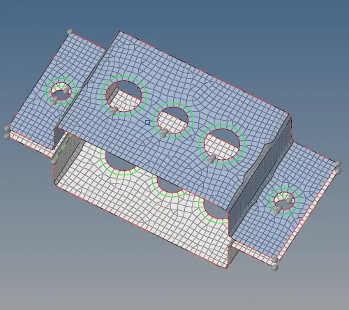
9.Rod=1D>rigid(RBE2)>multiple nodes>calculate node>by path translational motion in x,y,z is constrained >create nodes around the circular area A
10.Beam=1D>REB3>All DOF's is contrained>nodes>by path>create nodes around circular area B
11.Bar=1D>REB3>only x&y DOF's is constrained>nodes> by path>create nodes around circular area c
12.1D>rigids>multiple nodes>calculate node>by path DOF's 3>create nodes around circular areas D&E
13.Now we have to create the cross section for rod ,beam and bar as per given dimensions
14.1D>hyperbeam>standard section>standard section type>standard section I>enter all the dimensions for beam element and rename it as beam
15.Entities>create>standard section>optistruct>cross>enter all the dimensions for bar element and rename it as bar
16.Entities>create>standard section>optistruct>box>enter all the dimensions for rod element and rename it as rod
17.Assigning the properties for beam,bar and rod
18.Tab bar>create>property>Beam>change card image to>PBEAM>material>steel>beam section>Beam
19.Tab bar>create>property>Bar>change card image to>PBAR>material>steel>beam section>Bar
20.Tab bar>create>property>Rod>change card image to>PROD>material>steel>beam section>Rod
21.1D>rods>element type=CROD>property>Rod>select the nodes in region A>CROD element is created
22.1D>bars>element type=CBEAM>property>beam>select the nodes in region B>CBEAM element is created
23.1D>bars>element type=CBAR>property>bar>select the nodes in region C>CBAR element is created
24.1D>masses>MASS=10>element types=CMASS1>select the nodes in the region D>create
25.1D>masses>MASS=10>element types=CMASS1>select the nodes in the region E>create
26.1D>springs>element types=CELAS1>select the corner nodes in both side of the F region>spring element is created
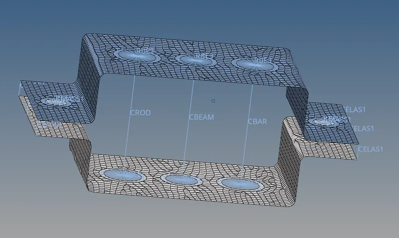
27.click on 1D detailed element represtation tool ,
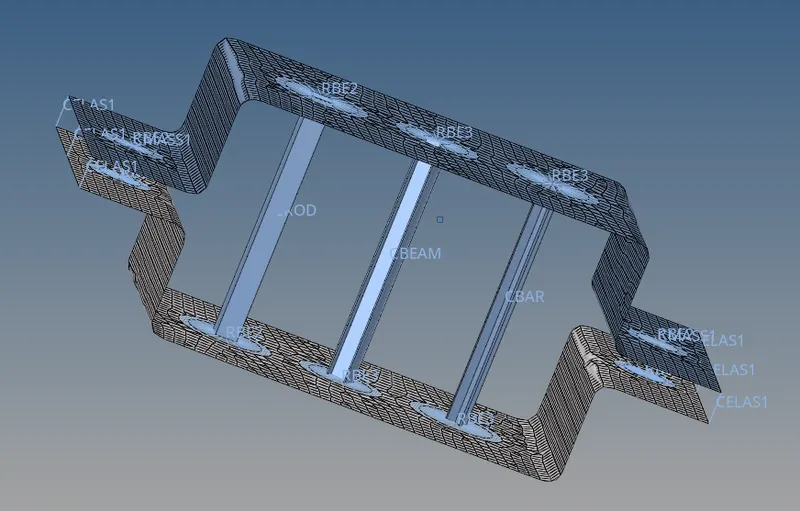
28.Hence the bar,beam and rod will be projected ,the final image is below
Conclusion:-
a)The objectives of the task has been achieved by generating the mesh in component, creating the 1D elements Rod(box),Beam(I section) and Bar(x section ) with the respective degree of freedoms and at its regions A,B,C.
b)And the D&E regions has been given the mass magnitude of 10 with RBE2 link
c)Finally the F region as been attached with the springs in corner nodes of the component