Week 4-1D Element Creation Challenge
1D Element Creation Challenge Report
Aim:
To create mesh on the given model by taking the mid surface and creating 1D elements on the following components with the given cross-section and DOF.
Procedure:
Mid Surface Extraction:
For mid-surface extraction, the given model was imported into Hypermesh software using the IMPORT GEOMETRY option under the IMPORT tab.
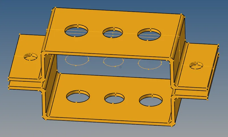
Fig. 1 CAD Model imported into Hypermesh.
For the mid surface to be extracted, we must first ensure that the thickness of the given model is uniform throughout the model. It was observed that the given has a uniform thickness of 5mm throughout. So using the AUTO MIDSURFACES option from the GEOMETRY menu tool was used.
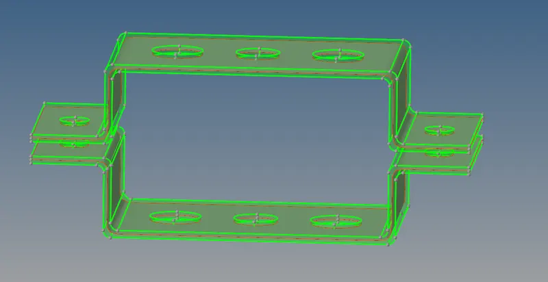
Fig. 2 Mid Surface extracted from CAD.
After mid surfaces were extracted, separate properties and material along with thickness were created and assigned to the mid surface.
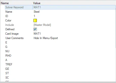
Fig. 3 Material Card created.
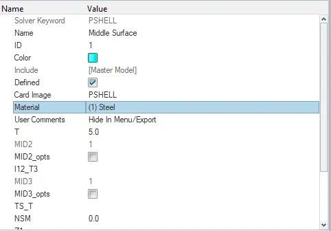
Fig. 4 Property Card with Thickness created.
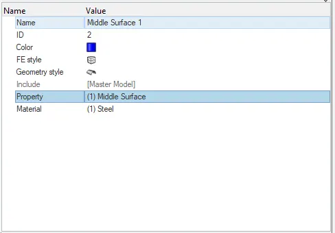
Fig. 5 Mid Surface 1 assigned with all properties.
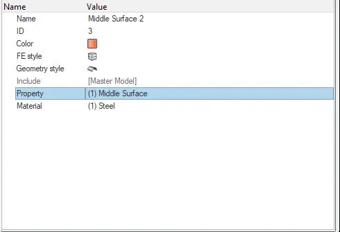
Fig. 6 Mid Surface 2 assigned with all properties.
Mesh Generation:
After mid-surface extraction, washer splits were made around the holes, and meshing was carried out on the mid-surface with an element size of 5mm.
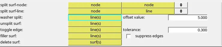
Fig. 7 Washer Split Option used near the holes.
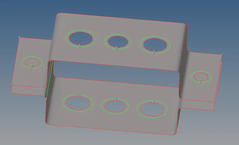
Fig. 8 Washer Split created near the holes.
Figure 9 shows the mesh created on the mid-surface of the CAD model.
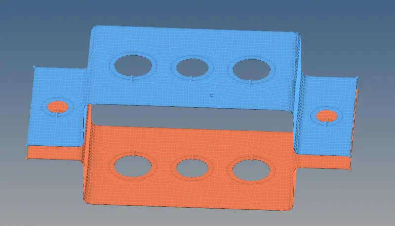
Fig. 9 Mesh created on the Mid-Surface extracted.
1D Element Creation:
Generally, 1D Elements include a bar, beam, rod, spring, rigids, and connectors. In this model, RBE2 and RBE3 elements were used to create bar, rod, spring, and beam as 1D elements. The following 1D elements were created at the specified component with specified dimensions and DOF. For
- Rod element:- Translational DOF Constrained with RBE2 link;
Cross-Section: BOX- Dimension a= 12 mm, dimension b=10 mm, and Thickness t= 0.75 mm.
- Beam element:- All DOF should be constrained with the RBE3 link;
Cross-Section: I Section- Dimension a= 8 mm, Dimension b= 10 mm, Dimension c= 8.5 mm, Thickness t1= 0.75 mm, Thickness t2= .6 mm, and Thickness t3= .6 mm.
- Bar element:- Constrain only x and y DOFs With the RBE3 link;
Cross-section: X section- Dimension DIM1= 5 mm, Thickness DIM2= 1.2 mm, Dimension DIM3= 10 mm, and Thickness DIM4= 1.2mm
For Rod elements, RBE2 links were created on the upper and bottom surface holes with specified DOF as shown in figure 10.
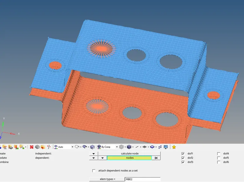
Fig. 10 RBE2 elements created for Rod.
For Beam and Bar elements, RBE3 links were created on the upper and bottom surface holes with specified DOF for each as shown in figures 11 & 12.
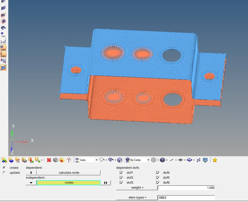
Fig. 11 RBE3 elements for Beam.
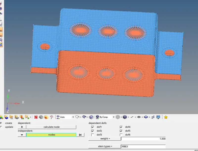
Fig. 12 RBE3 elements for Bar.
The cross-sections and properties for the road, beam, and bar elements were created and assigned respectively. The following figures show the cross-section and properties of each respectively.
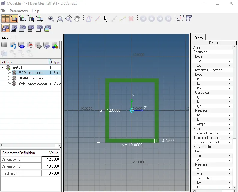
Fig. 13 Rod – box section.
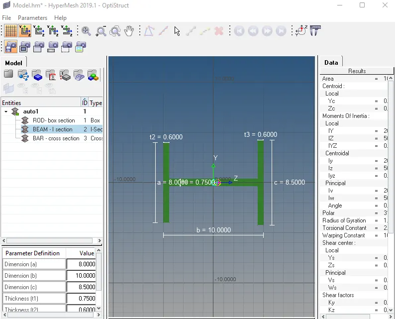
Fig. 14 Beam – I section.
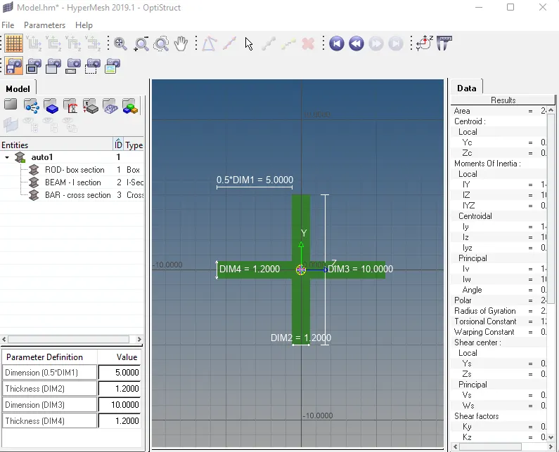
Fig. 15 Bar – X section.
The properties of the rod, beam, and bar were created and shown below.
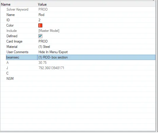
Fig. 16 Rod Element’s property created.
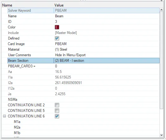
Fig. 17 Beam Element’s property created.
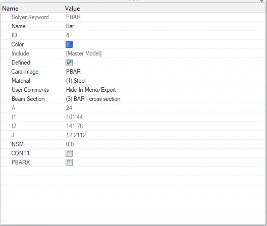
Fig. 18 Bar Element’s property created.
The 1D elements namely, Rod, Beam, and Bar elements were created and assigned with their respective properties.
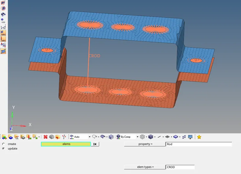
Fig. 19 Rod Elements with properties created.
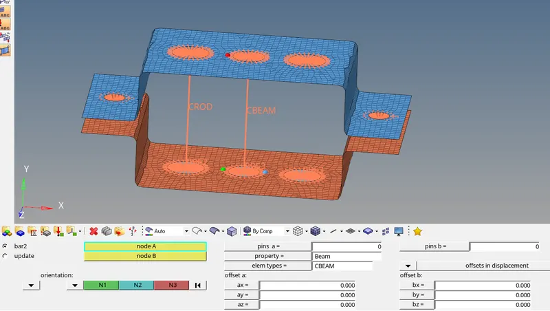
Fig. 20 Beam Elements with properties created.
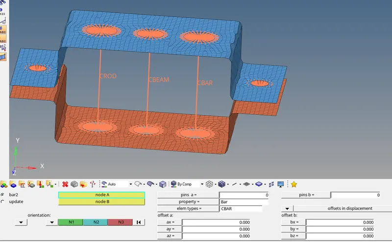
Fig. 21 Bar Elements with properties created.
Then the other components namely d & e were applied with the mass of magnitude 10 with CMASS1 using the RBE2 link and f was joined with Spring elements.
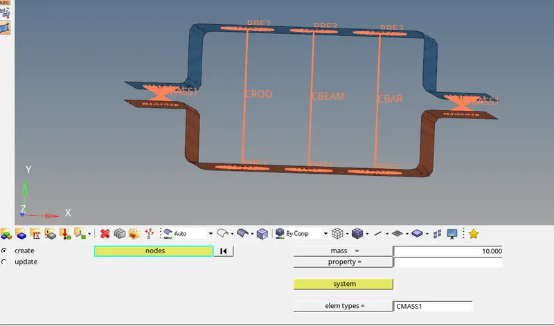
Fig. 22 CMASS1 added to the holes using RBE2 links.
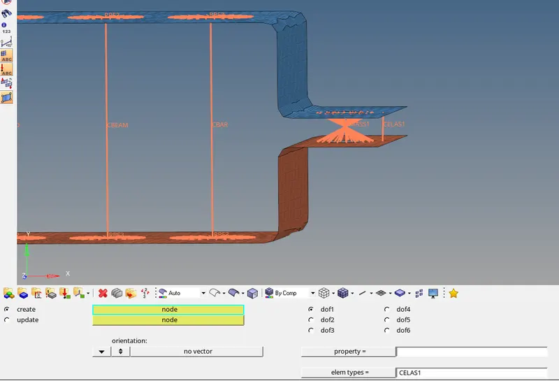
Fig. 23 The two mid-surfaces were joined using spring elements at both ends.
After creating all the elements specified, the thickness was activated and 1D elements were represented in a real cross-section assigned. Figure 24 shows the completed entire model with all the given data and figure 25 shows the model in real cases.
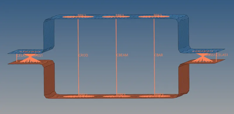
Fig. 24 Complete Model.
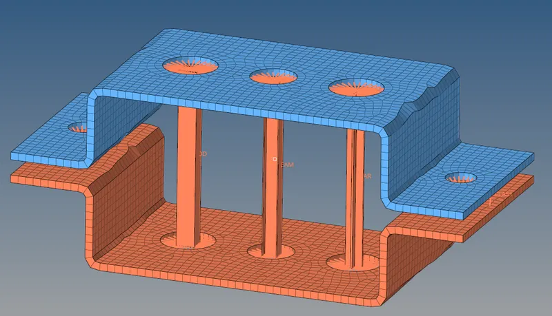
Fig. 25 Final Output Model.
Results:
The Mid-surface was successfully extracted from the CAD Geometry and mesh was generated on the extracted mid-surface where material and other properties were assigned. Thereafter holes were connected using RBE2 and RBE3 link elements.
Later 1D elements were created with the given dimensions and DOF with their respective properties created and assigned to them. Finally, a mass of magnitude of 10 was applied using RBE2 link elements on either end hole and the two mid surfaces were joined using spring elements.