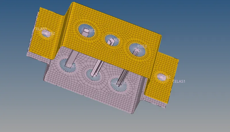
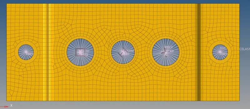
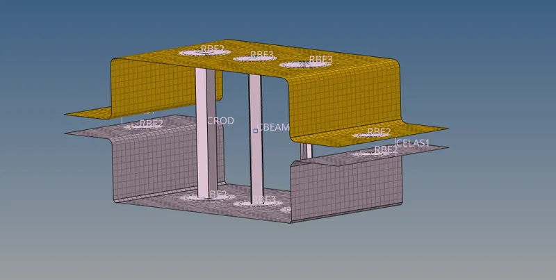
Week 4-1D Element Creation Challenge
MODULE1
introduction to bar rod and beam
Rod is a member which is Circular In cross-section. But Bar can be of any cross section like a rectangular bar, square bar, I- section bas etc. But a Beam Can be of any cross section either circular or any other.
The main difference between Bar/Rod & Beam is in the basis of loading conditions.
A rod and Bar are subjected to Axial load only, this can be either tensile or compressive but not torsion or bending.
And a Beam can be subjected to any type of load, tension compression, torsion and bending, shear etc.
So if u have a bar or rod subjected to tension and u addeed a bending moment on it then this will no more called as a bar, now it has become a beam.
Mesh the Given component with the Size of 5 Units. Create 1D elements on the following component with given cross-section and DOF
a. Rod element:- Translational DOF should be Constrained with RBE2 link
Cross-Section: BOX- Dimension a= 12 mm
dimension b=10 mm
Thickness t= 0.75 mm
b. Beam element:- All DOF should be constrained with RBE3 link
Cross-Section: I Section- Dimension a= 8 mm
Dimension b= 10 mm
Dimension c= 8.5 mm
Thickness t1= 0.75 mm
Thickness t2= .6 mm
Thickness t3= .6 mm
c. Bar element:- Constrain only x and y DOFs With RBE3 link
Cross-section: X section- Dimension DIM1= 5 mm
Thickness DIM2= 1.2 mm
Dimension DIM3= 10 mm
Thickness DIM4= 1.2mm
d. & e. Apply the mass of magnitude 10 with the RBE2 link
f. Join the two components with Spring elements
initially, we imported the cad model from model geometry into the hypermesh Gw
now we are going to check the model carefully by using the geometry clean up tool/auto cleanup following are the function of autocleanup tool
Clean the geometry: delete bad edges, delete temp nodes, fill surfaces, toggle edges with tolerances,
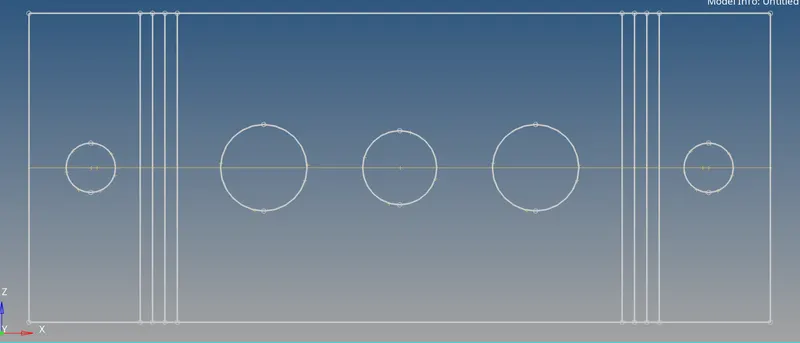
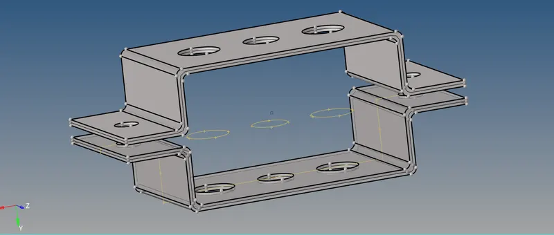
from the above model we are going to extract the mid surface
mid surface is the surface between the two surfaces also we can say its a 2d representation of 3d elements.we do mid surfacing in order to minimize the number of nodes which in turn minimize the number of elements hence the analysis time and storage will be less
mid surfacing can be done where the thickness is constant and also acts as a neutral axis
elements that we are going to use for meshing are 2D
2D elements:trias and quad elements
in the above model, we are going to use a 1D bar, Rod and Beam
streps
once the imoprt and autocleanup is done the next step is to extract the mid surface
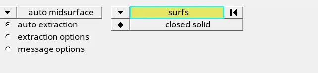
TO extract the mid surface click on geo>select the midsurface >select the auto extraction >select the surface you want to extract the mid surface .
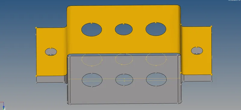
we have extracted the mid surface for component 1 and named as bracket 1 .in order to extract the mid surface for the 2nd component, we are going to create the component first and rename it to bracket 2 .
now extract the mid surface from component 2nd, once this is done assign this mid surface to bracket 2 that we have already created .so to assign mid surface to bracket 2 we have to click on tools from there we are going to select the organize >click on collector >click on the surface that we want to move and click on move.
now the mid surface is assigned to bracket 2 and make sure we have selected the component that we want to assign.
delete the mid surface that we have already as we have assigned this to bracket 2
delete the solid geometry we did not need that now
keep only brackets 1 and 2
MESHING
now we are going to mesh the extracted mid surface in order to do this first we are going to create a washer around circular section click>F11
select washer split >set offset value 10 and click to create
go panel click on 2D >click on auto mesh >select the surface
click element size =5mm
click element type =select guard


we have successfully done meshing to all components
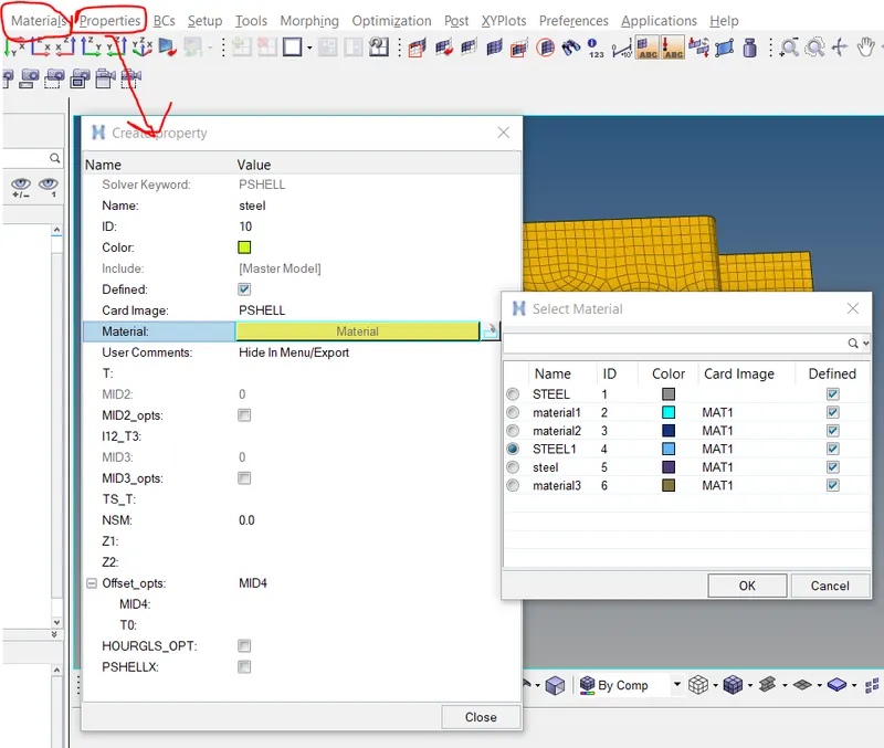
to create material select materials from the menu bar and set card image MAT1 and name as steel and set the remaining properties as default
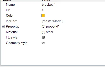
now we have to assign material and property to the bracket 1 and 2 for that we have to create material.click on the property from the menu bar and create property,in property panel select card image as PSHELL and select material as steel and give name as bracket 1
similar process for 2nd component named as bracket 2
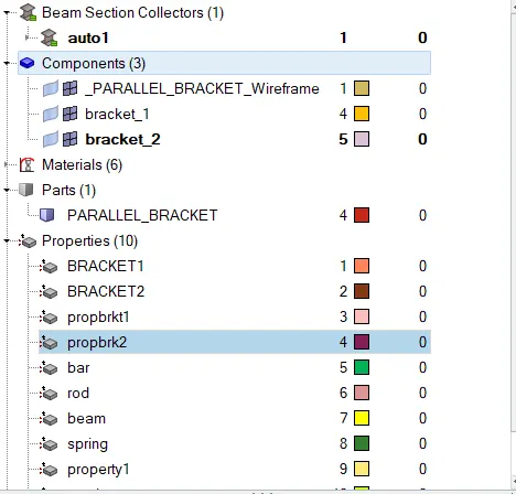
now properties are created named as bracket 1 and bracket 2
now click bracket 1 and assign thickness =2mm and select material as steel
similarly, we can assign material and properties to bar rod and beam
now we have to create 1D -RBE2(riged) LINK and RBE3 LINK
click on 1D from pannel >select rigids >select creat option> select calculated nodes> select node by path and click on the surface where we want to create RBE2 LINK (around the circular section).untick the translational DOF for first case .
similar is the process for RBE2 link and spring


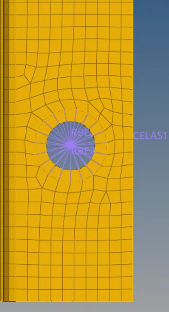
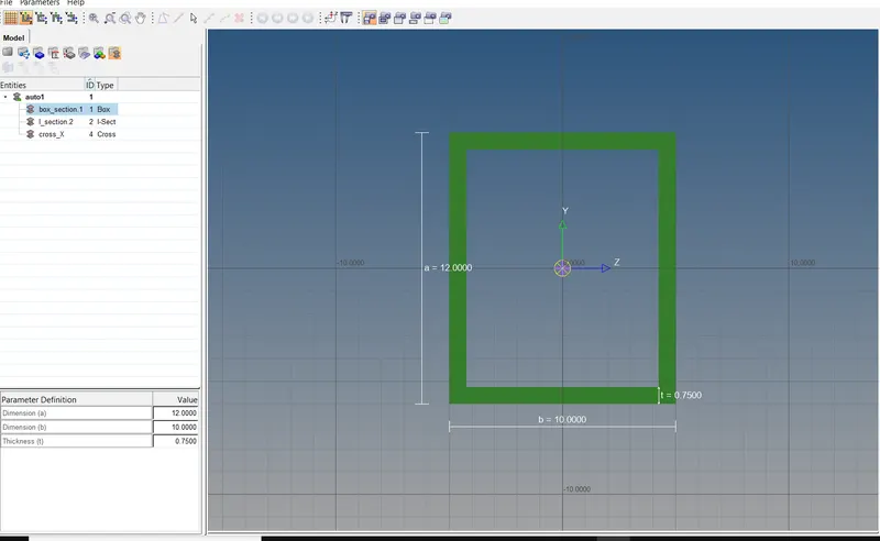
now we are going to create hyperbeam click 1D >select hyperbeam>select standard section >click on standard section and select hyper beam this will take us hyper beam window

case 1
a. Rod element:- Translational DOF should be Constrained with RBE2 link
Cross-Section: BOX- Dimension a= 12 mm
dimension b=10 mm
Thickness t= 0.75 mm
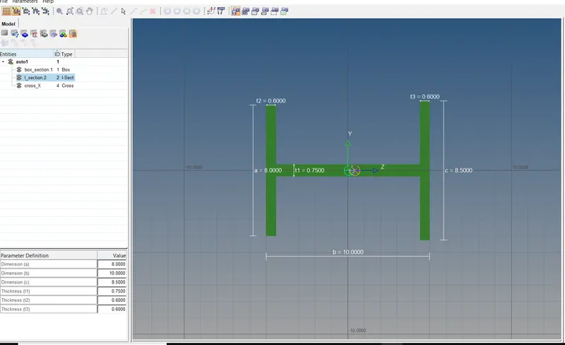
b. Beam element:- All DOF should be constrained with RBE3 link
Cross-Section: I Section- Dimension a= 8 mm
Dimension b= 10 mm
Dimension c= 8.5 mm
Thickness t1= 0.75 mm
Thickness t2= .6 mm
Thickness t3= .6 mm
c. Bar element:- Constrain only x and y DOFs With RBE3 link
Cross-section: X section- Dimension DIM1= 5 mm
Thickness DIM2= 1.2 mm
Dimension DIM3= 10 mm
Thickness DIM4= 1.2mm

now create properties for bar rod ,beam and spring as
PROD TO ROD
CBEAM TO BEAM
CBAR TO BAR
CELAS to spring
case 1
go to 1D >click bars>select the element CBAR >click on property and select bar>go to orientation select nodes for cross secction and click on update

similar is the process for ROD AND BEAM
case 4
d. & e. Apply the mass of magnitude 10 with the RBE2 link
click on masses >select element RBE2 (a and b cross-section ) set 10 units mass to these links and click on update
f. Join the two components with Spring elements
go to 1D >select spring>select node at one edge of one component and select the other noade at the edge of 2nd component select dof 2(along y axis) and click on create
final snaps of the model
in order to view the cross section of the beam bar and rod click 1d detailed element representation