Week 4-1D Element Creation Challenge
Aim :
- Create the 1D elements
Objective :
Mesh the Given component with the Size of 5 Units. Create 1D elements on the following component with given cross-section and DOF
a. Rod element:- Translational DOF should be Constrained with RBE2 link
Cross-Section: BOX- Dimension a= 12 mm
dimension b=10 mm
Thickness t= 0.75 mm
b. Beam element:- All DOF should be constrained with RBE3 link
Cross-Section: I Section- Dimension a= 8 mm
Dimension b= 10 mm
Dimension c= 8.5 mm
Thickness t1= 0.75 mm
Thickness t2= .6 mm
Thickness t3= .6 mm
c. Bar element:- Constrain only x and y DOFs With RBE3 link
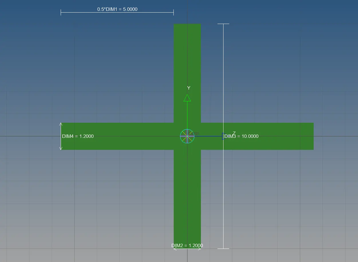
Cross-section: X section- Dimension DIM1= 5 mm
Thickness DIM2= 1.2 mm
Dimension DIM3= 10 mm
Thickness DIM4= 1.2mm
d. & e. Apply the mass of magnitude 10 with the RBE2 link
f. Join the two components with Spring elements
First Objective :
link of 1d_element _creation_file :https://drive.google.com/file/d/1HFQsk5s9iFv0fAWHvwFk86SXQRsQLU5D/view?usp=sharing
- Mesh the given component with the size of 5 units
procedure:
1. import the Geometry
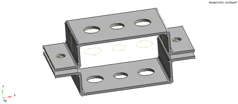
Create the surface from the Geometry or extract the mid surface [command: Geometry + mid surface + automidsurface ]
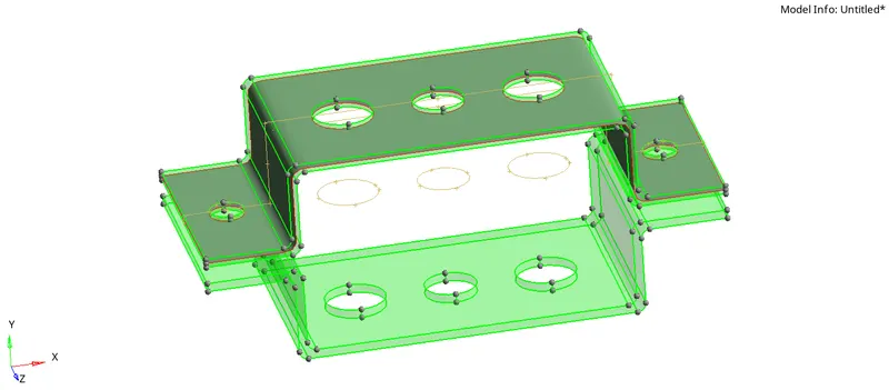
2. for the capture of good mesh to surface first, we need to extract the proper surface from the solid. Therefore I tried to use
skin offset from extraction option tab.
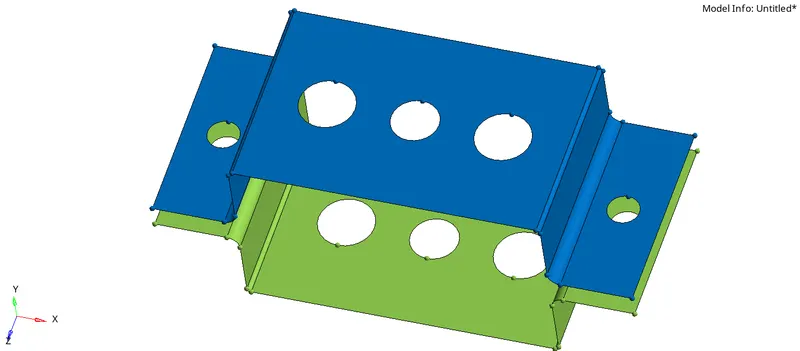
try to keep the separate mid surface for a separate component
Create the washer split each hole of 5 unit values [command: geometry + quick edit + washer split]
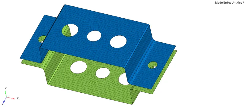
Then create the 2D mesh of element size as 5 units [command: 2D + automesh + mesh type (mixed)]
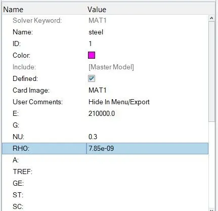
3. create the material give the name steel and do changes as given image
As we created the 2D element from the 3D it is just a representation of a 3D element called a shell element so we should have to give thickness
Create the property for bracket 1, bracket 2 and give the thickness as 2 units.
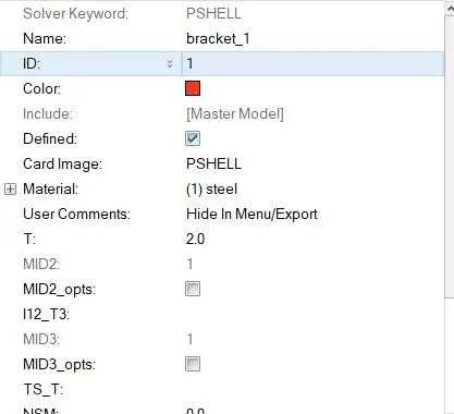
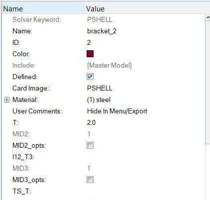
Apply those properties for bracket 1 surface and bracket 2 surface
Second Objective :
Create 1D elements on the following component with given cross-section and DOF
1. Create the RBE 2 link at a hole 'a' with Constrained translational DOF
[commands: 1D+Rigids+Create+(change dependant to multiple nodes and independent to calculate nodes) ]

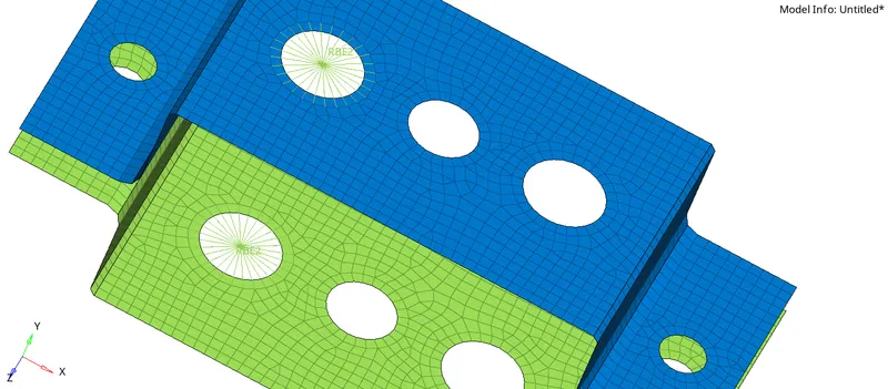
2. Create the RBE3 links for holes 'b' where all DOF constrained and for hole 'c' X and Y DOF constrained

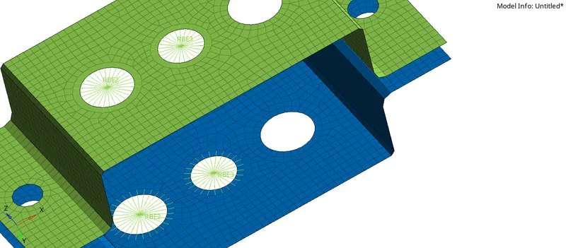

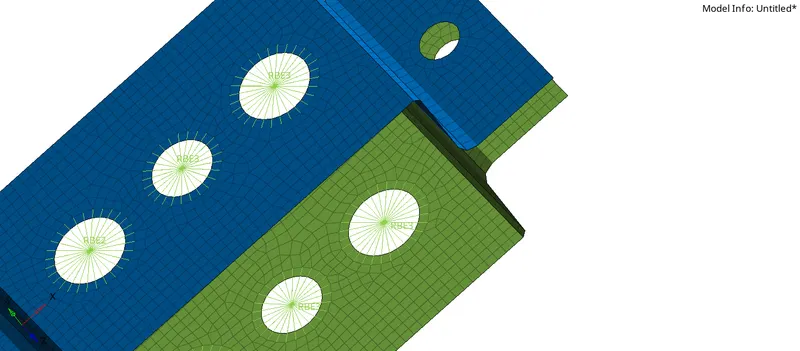
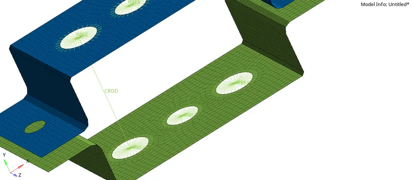
3. Create a 1D ROD element for hole 'a' with the RBE2 link [command: 1D + rods + element type (CROD)]
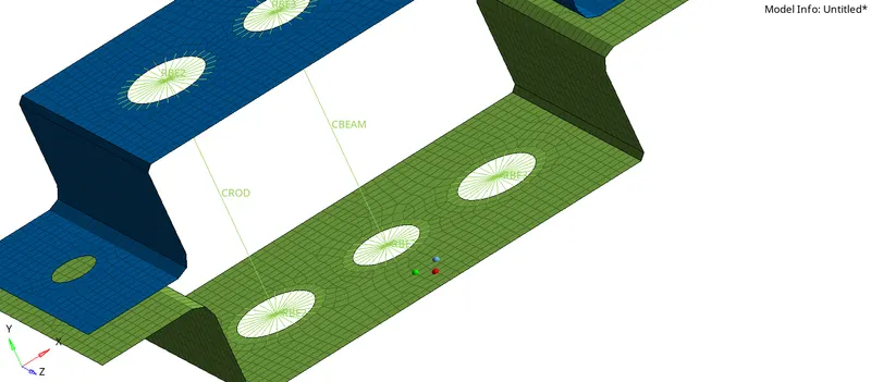
4. Create Beam element for hole 'b' with RBE3 link [command : 1D + bars + element type(CBEAM)]
5. Create Bar element for hole 'c' with RBE3 link [command : 1D + bars + element type(CBAR)]
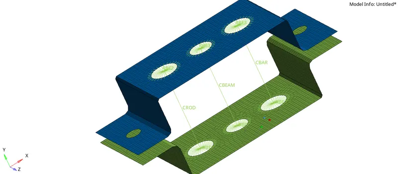
6. Create the RBE2 link at a hole 'd', 'e' and Apply the mass of magnitude 10 with the RBE2 link.
[ command : 1D + masses +element type (CMASS1) ]
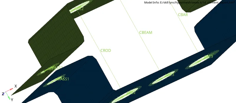
7. Create BOX cross-section, I section, X section as per the given dimensions.
[command : 1D + hyperbeam + standard section + select section + create ]
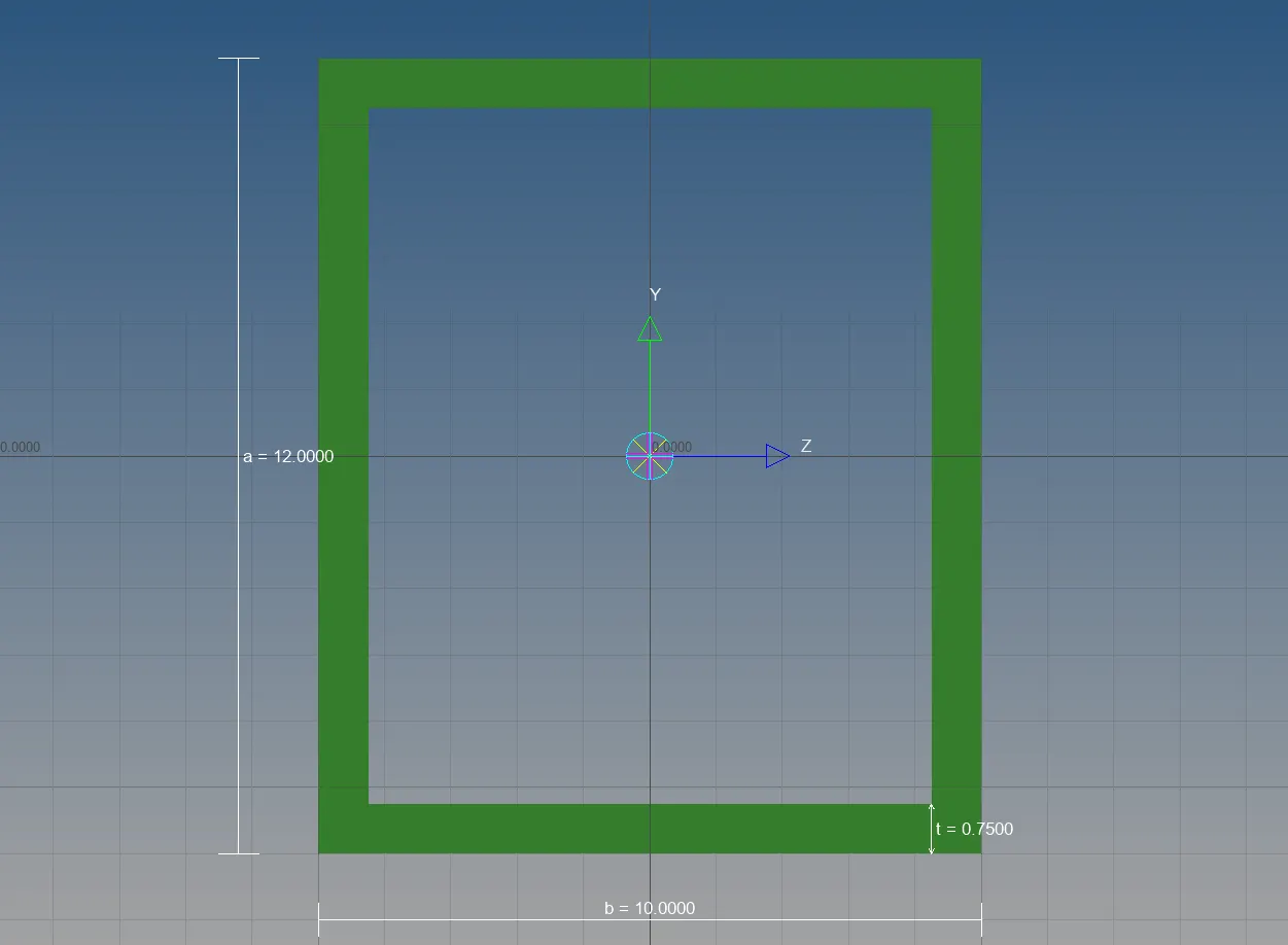
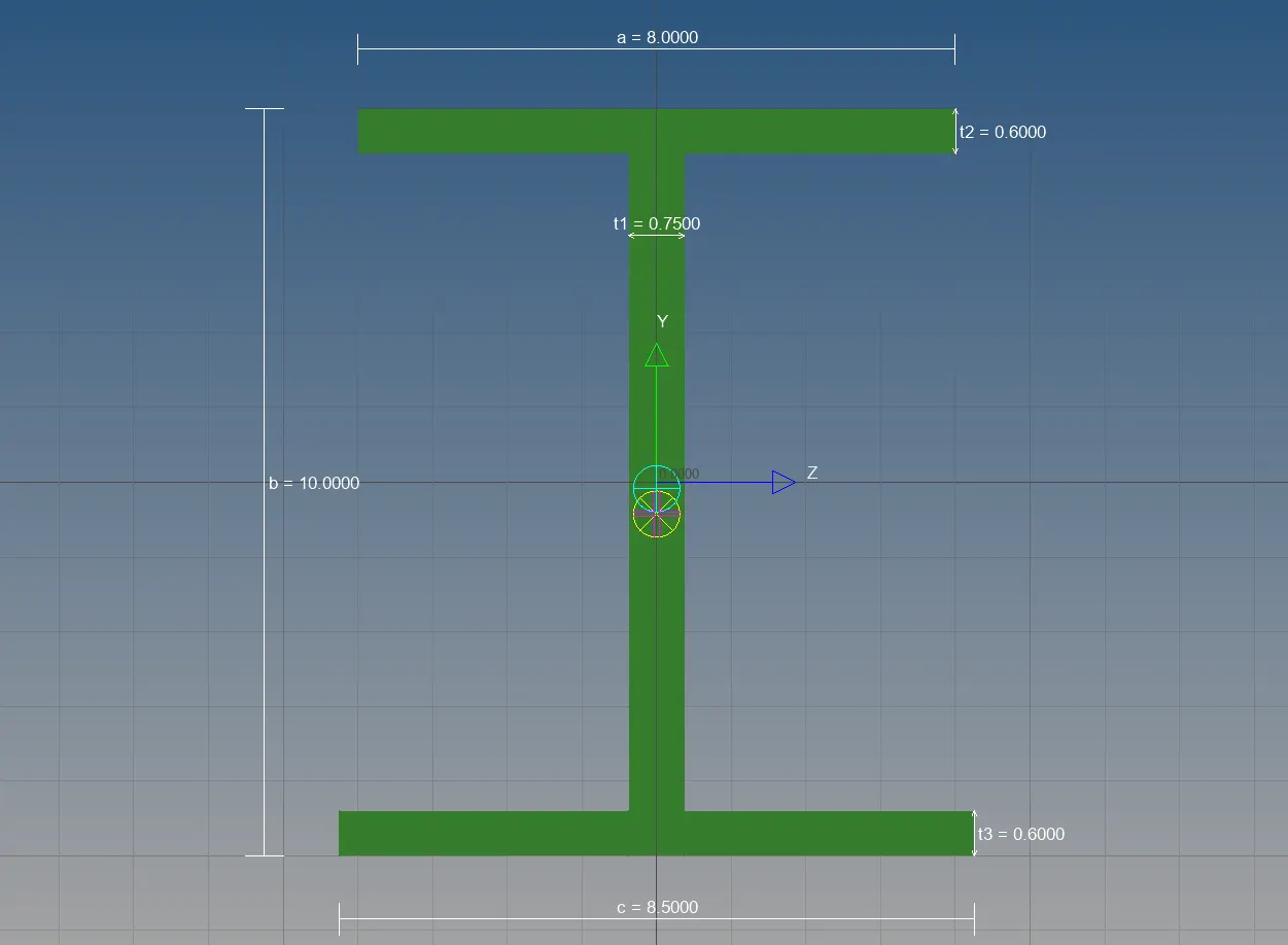
8. Create the property for ROD, BEAM, BAR elements and change the card image, beam section as per the given images
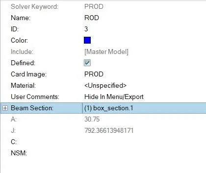
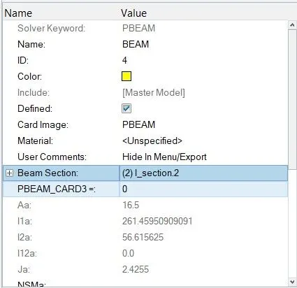
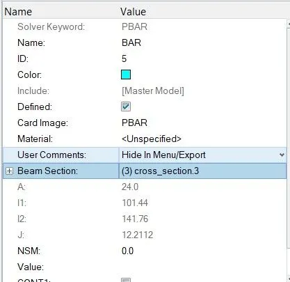
9. Apply those properties to elements
for ROD element [command: 1D + rods + update + property(ROD) and element type (CROD)]

for BEAM element [command: 1D + bars + update + property(BEAM) and element type (CBEAM)]

for BAR element [command: 1D + bars + update + property(BAR) and element type (CBAR)]

for visualization of applied cross-section click on 1D Detailed element representation
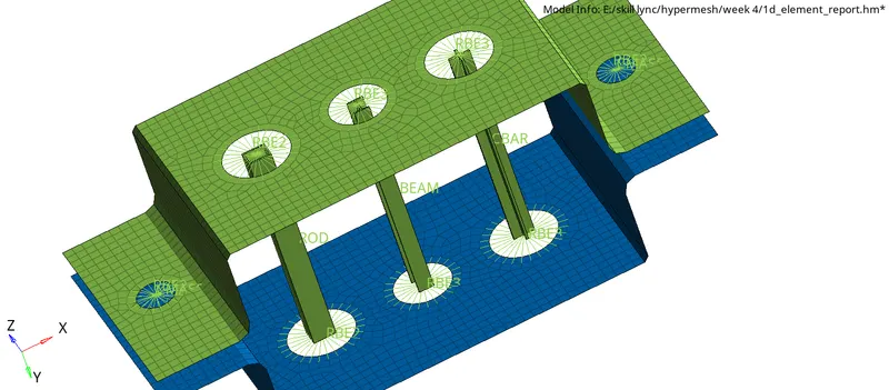
10. Join the two components with Spring elements
[command:1D + springs +select the nodes]
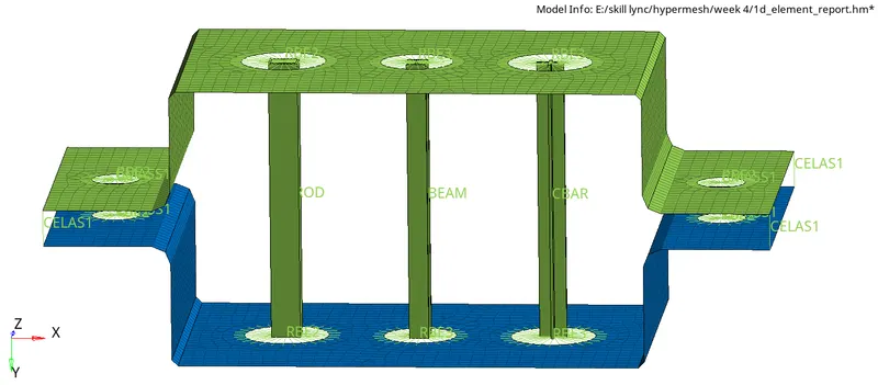
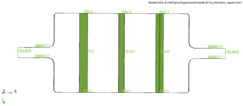
11. 2D detail element representation
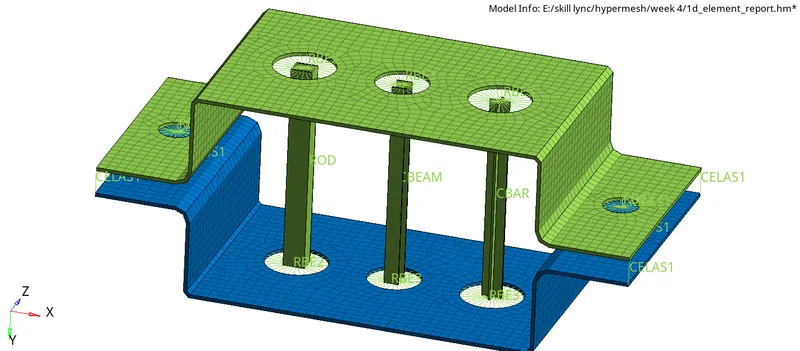
Conclusion :
- Extracted mid surface from the model and created the 2d mesh
- Created the RBE2 and RBE3 links for the holes
- Created the 1D elements and applied the masses to the RBE2 links