Week 4-1D Element Creation Challenge
PARALLEL BRACKET.
OBJECTIVE: 1) To create a mid-surface and meshing.
2) Creation of 1D elements like bar, rod, beam, spring, rigid and RBE3 elements.
PROCEDURE: 1) Import given CAD model in hyperworks desktop student version.
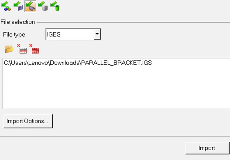
IMPORT MODEL→IMPORT GEOMETRY→FILE TYPE(IGES)→SELECT LOCATION → CLICK ON IMPORT→ FIT (PRESS F).
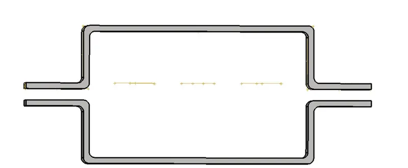
2) Since thickness of the bracket is 5mm we can create a mid-surface. Before creating delete the solids because we do not require.
DELETE→SOLIDS→ALL→DELETE SELECTED ENTITY→CONFIRM.
Now, we can move the entire parent geometry in one collector.
TOOL→ORGANIZE→SELECT SURFACES →MOVE
Now we can delete the empty collector.
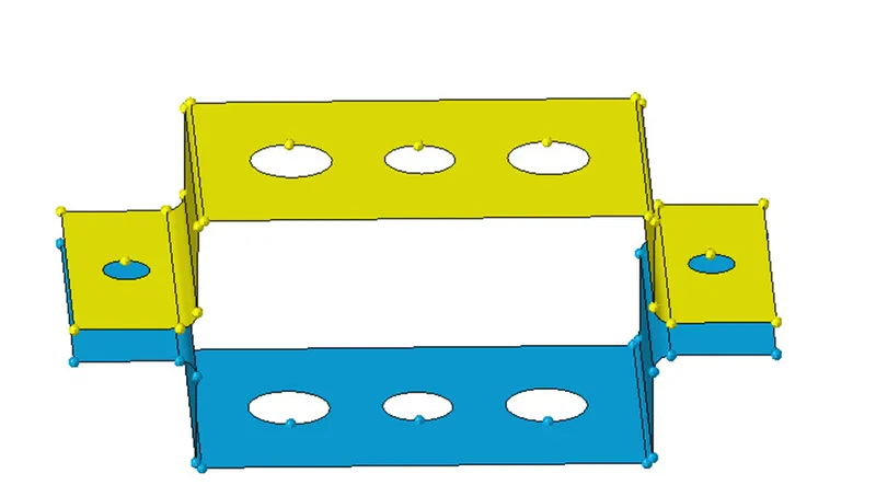
3) Now we will create a mid-surface for both the parallel brackets separately and name it as bracket1 and bracket2.
GEOMETRY→MID-SURFACE→ AUTOMIDSURFACE→ EXTRACTION OPTIONS (SKIN OFFSET) → AUTOEXTRACTION→ SELECT THE SURFACES → CREATE→ GIVE COLOR.

4) Create a material card.
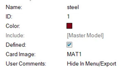
LEFT CLICK→CREATE→MATERIAL→RENAME (STEEL).
5) Create a property card for both mid-surface bracket 1 and bracket 2. Select the card image as PSHELL and enter the thickness value as 5.
LEFT CLICK→ CREATE→PROPERTY→ SELECT THE CARD IMAGE AS PSHELL AND ENTER THE THICKNESS VALUE AS 5.
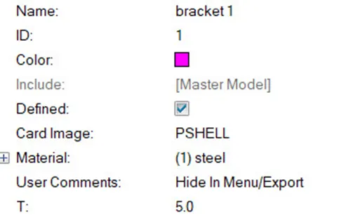
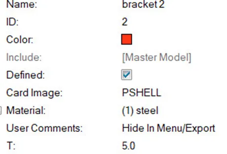
6) Now, after creating material and property card assign it to both the component.
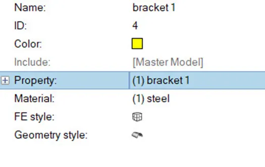
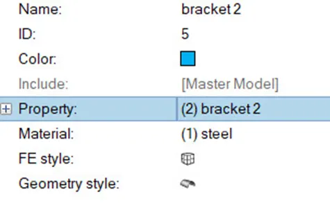
7) Now, create a washer split at the holes. It is created to reduce the stress concentration.
GEOMETRY→QUICK EDIT→WASHER SPLIT→ENTER THE OFFSET VALUE→CONFIRM.
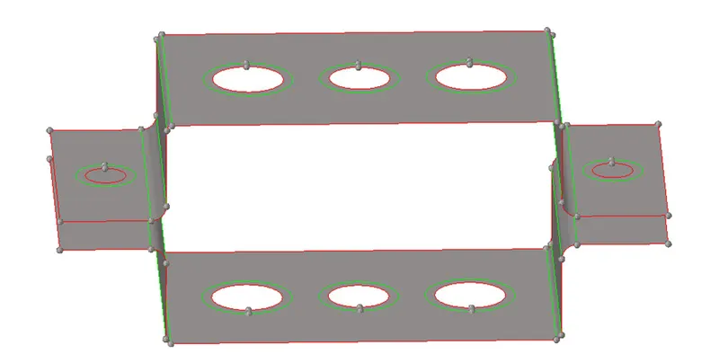
8) Now we will mesh both the parallel bracket one at a time.
2D →AUTOMESH→ENTER THE ELEMENT SIZE (5) →SELECT THE SURFACE→CREATE.
NOTE: Remember while meshing on bracket 1 in model section you must select bracket 1. Suppose if we select bracket 2 instead of 1 then mesh element generated on bracket 1 will be associated with bracket 2.
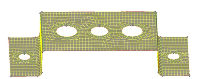
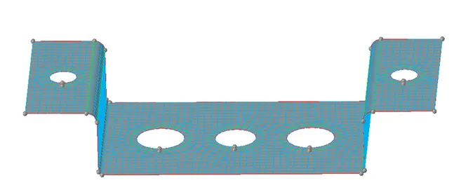
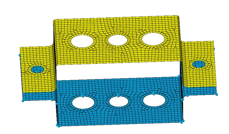
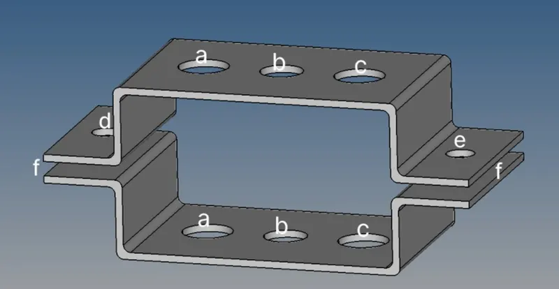
9) Now, as we see in above image first, we will create RBE2 elements at d and e.
1D→RIGID→CALCULATE NODES→MULTIPLE NODES→SELECT THE PERIMETER NODES AND WASHER SPLIT NODES BY PATH SELECTION OR WINDOW SELECTION→CREATE.
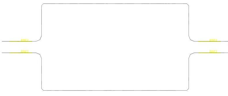
10) Now, apply mass of magnitude 10 at the master nodes of RBE2 elements.
1D→ MASSES→ENTER THE VALUE AS 10→SELECT MASTER NODE→CREATE.

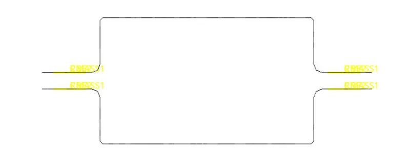
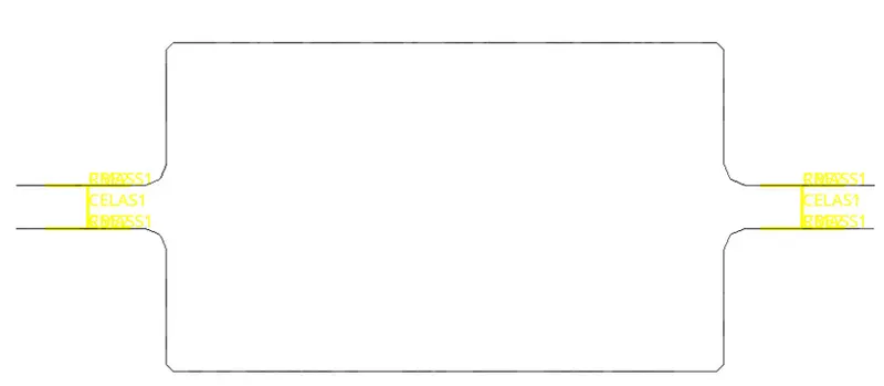
11) Now, we will join both the components by spring element. i.e. f.
1D→SPRING→SELECT THE MASTER NODES→CONFIRM.
12) Now we will first create a cross section area for bar, rod and beam element.
1D→HYPERBEAM→STANDARD SECTION→STANDARD SECTION LIBRARY (OPTISTRUCT/ HYPERBEAMS) → STANDARD SECTION TYPE (AS PER THE REQUIREMENT) →CREATE.
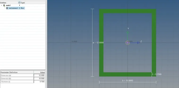
For rod,
Standard section library: hyper beams
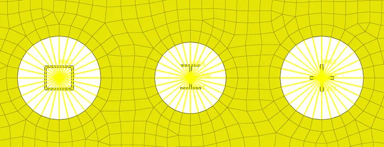
Standard section: thin-walled box.
Enter the dimension as: a=12, b=10 and t= 0.75.
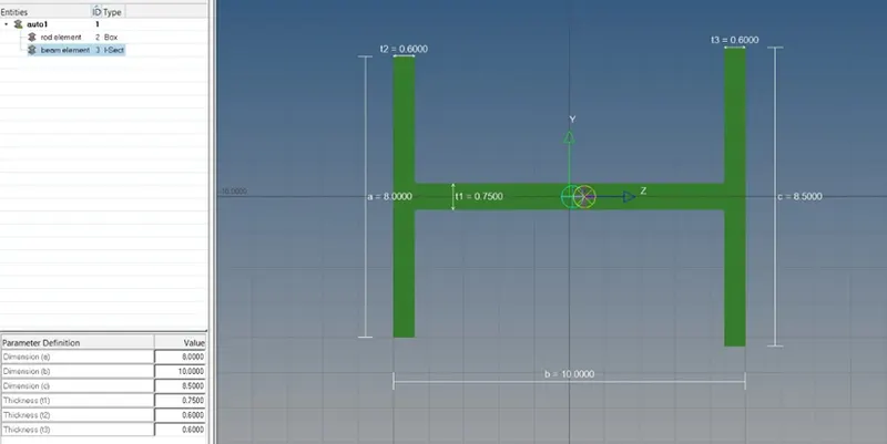
For Beam,
Standard section library: hyper beams.
Standard section: I-section.
Enter dimensions as: a=8, b=10, c=8.5, t1=0.75, t2=0.6 and t3=0.6
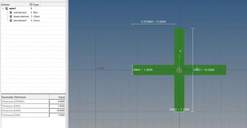
For bar,
Standard section library: Opti struct.
Standard section: cross.
Enter dimension as: D1M1=5, D1M2=1.2, D1M3=10 and D1M4= 1.2
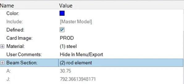
13) We will create property for bar, rod and beam and enter the card image as PBAR, PROD and PBEAM. Also specify the material.
LEFT CLICK→ CREATE→PROPERTY→SELECT THE CARD IMAGE (PBAR/PROD/PBEAM) → SPECIFY THE MATERIAL→SECTION →OK.
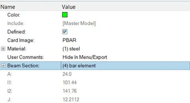
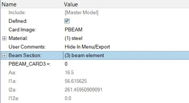
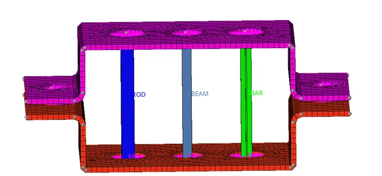
14) Now, we will create RBE2 element at a (where rod element needs to be created) by keeping only transitional degree of freedom constrained and create a rod element.
1D→RIGIDS→SELECT THE NODES → UNMARK ROTATIONAL dof → CONFIRM.
1D→RODS→SELECT THE MASTER NODES→PROPERTY (ROD)→ELEMENT TYPE AS (CROD)→CREATE.


15) Now we will create RBE3 element at b (where beam elements need to be created) by keeping all dof constrained. And also create beam element.
1D→RBE3→SELECT THE NODES (BY PATH OR WINDOW SELECTION) →CONFIRM.
1D→BAR→SELECT THE MASTER NODES→PROPERTY(BEAM)→ELEMENT TYPE(CBEAM)→CONFIRM.


16) Now we will create RBE3 element at c (where bar element needs to be created) by keeping only x and y dof constrained. And also create a bar element.
1D→RBE3→SELECT THE NODES (BY PATH OR WINDOW SELECTION) →UNMARK dof FOR Z→ CONFIRM.
1D→BAR→SELECT THE MASTER NODES→PROPERTY(BAR)→ELEMENT TYPE(CBAR)→CONFIRM.


17) Enable to 2D and 1D detailed element representation.
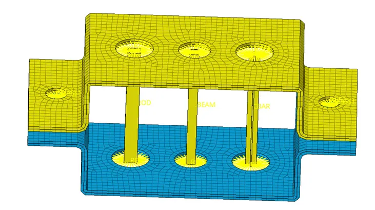
Difference between RBE2 and RBE3 element:
|
RBE2 |
RBE3 |
|
It is a rigid element and all the nodes are constrained. |
Nodes can be move and can be translated where load is applied. |
|
Load distribution is uniform. |
Node closes to mass will have more load than node farther from the node where load is applied. |
|
RBE2 elements cannot have materials. |
RBE3 elements can have material assigned. |
Difference between Rod, Bar and Beam.
|
|
ROD |
BAR |
BEAM |
|
Based on area of cross section |
Circular |
Non-circular like rectangular, square, I section bar etc |
It can be of any shape either circular or rectangular, square etc. |
|
Based on type of loading |
Axial load irrespective of compressive or tensile but it should not be torsion or bending. |
Axial load irrespective of compressive or tensile but it should not be torsion or bending. |
It can be subjected to any load such as tensile, compressive etc. |
LEARNING OUTCOMES: 1) Creation of 1D element like bar, beam, rod, RBE2 and RBE3 elements.
2) Difference between RBE2 and RBE3 element.
3) Difference between BAR, ROD and BEAM.
4) To assign cross section to different element like rod, bar and beam.
5) To create property and material card.
CONCLUSION: Hence mid-surface and meshing is generated and 1D element is created.