Week 4-1D Element Creation Challenge
Objective:
- To create mesh with the size of 5mm.
- To create 1D elements on the given component with cross-section and DOF.
Procedure:
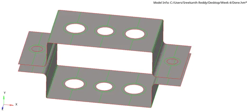
Given model:
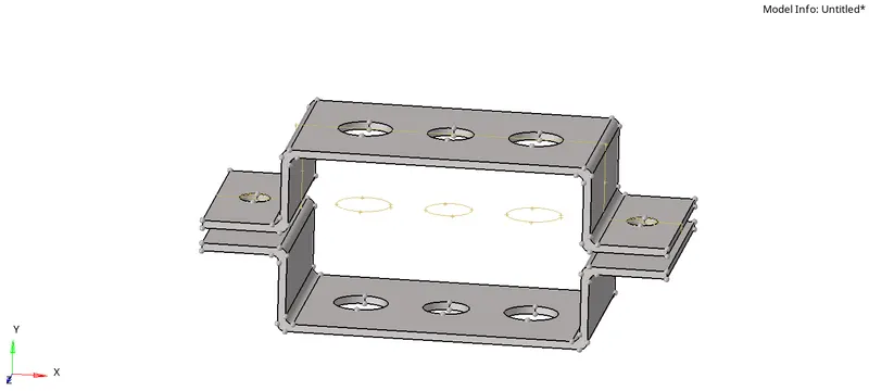
We can see there are extra geometry in the given model.
Delete the extra component given.
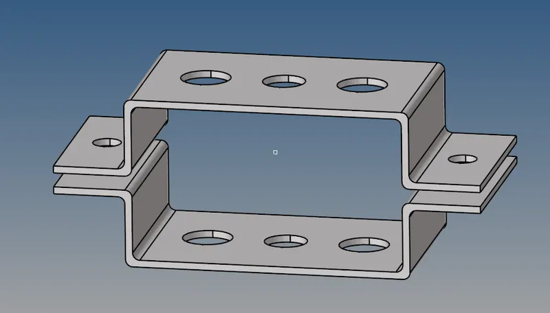
Go to geometry >>> Auto cleanup >>> Maintain the target element size to 5mm as given (provide the value in parameters >>> basic) >>> Auto cleanup.
The below image is after the Geometry cleanup:
Extracting the mid-surface:
Go to Geometry >>> Mid-surface >>> Auto mid surface >>> Extraction options >>> Skin Offset >>> Auto extraction >>> Extract.
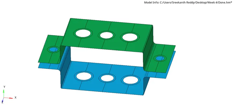
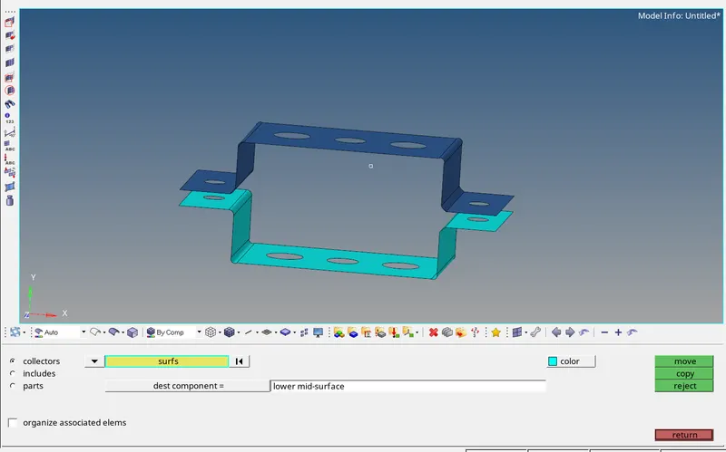
Prior to creating any new component in GUI, Go to Tab menu >>> Right click >>> Create >>> Component
If the above thing is not done prior, the alternative is to Go to tools >>> Organize >>> Select the surface to move >>> move (make the new component to which it has to be moves as current)
Create washer elements of size 5 mm.
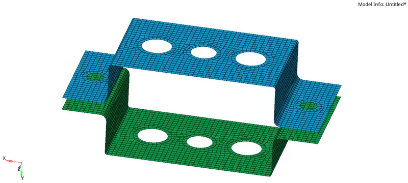
Go to 2D >>> Auto mesh >>> Target length=5mm >>> select the surfaces >>> Displayed
At the fillet region create 2 rows of elements to capture the fillet well.
At the washer region maintain same number of nodes in and out.
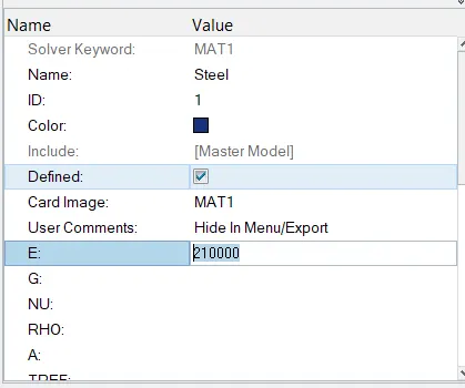
Create the material card
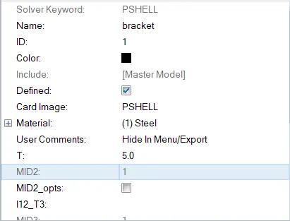
Create the property >>> Shell >>> Provide thickness
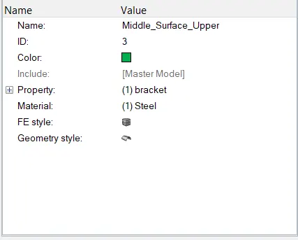
Assign the material and the property to the mid-surface components.
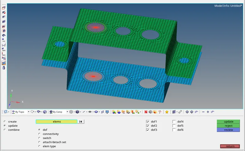
As given create RBE2 elements as shown below.
The multiple nodes are to be selected which are dependant nodes and independant node is automatically create at center of mass. If load is acted at the independant node, the same load is acted at the dependant nodes.
Degree of freedom is provided as given (All degrees are constrained)

If needed, we can check the degree of freedom provided from update and make changes if needed.
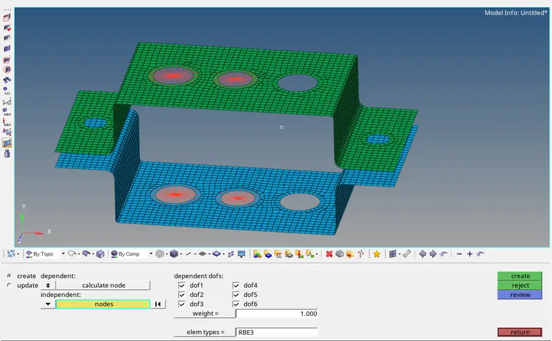
Similarly, create the RBE3 elements as given
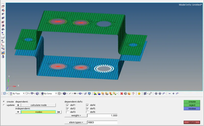
Go to 1D >>> Hyperbeam >>> Standard section >>> Select the section of your choice >>> create

I section
provide the dimentions as given
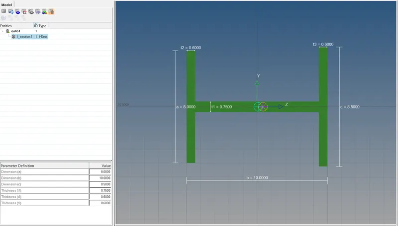
Right click on the tab menu to create and add new sections
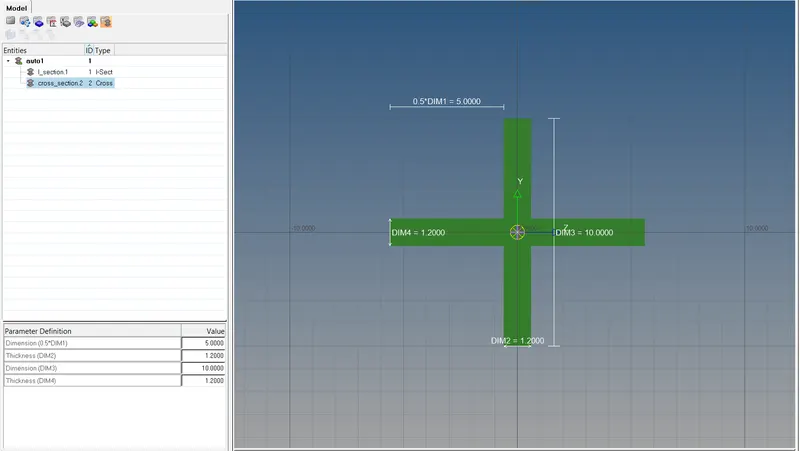
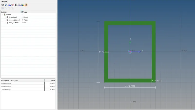
Create Properties for the respective rods, beams and bars
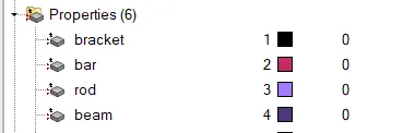
For the bar, Provide the card image as PBAR.
For the rod, Provide the card image as PROD.
For the beam, Provide the card image as PBEAM.
Now, Create the 1D elements :
Create the components namely bar, rod, beam.
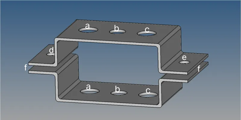
Rods - a
Beams - b
Bars - c
Apply the mass of magnitude 10 with the RBE2 link - d & e.
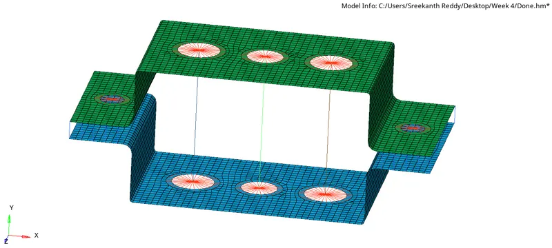
Go to 1D >>> Rods >>> Select the propery >>> Select the element type

Go to 1D >>> Bars >>> Select element type as cbeam >>> Select the propery >>> Select the element type

Go to 1D >>> Bar >>> Select element type as cbar >>> Select the propery >>> Select the element type

Assign the properties of their respective types to the rods, beams, bars.
At d. & e. Apply the mass of magnitude 10 with the RBE2 link:
Go to 1D >>> masses >>> Select the d & e master nodes of RBE2 >>> Assign mass of 10 units.
Create the property card for mass with card image as PMASS.
Join the two components with Spring elements:
Go to 1D >>> Springs >>> Select the nodes
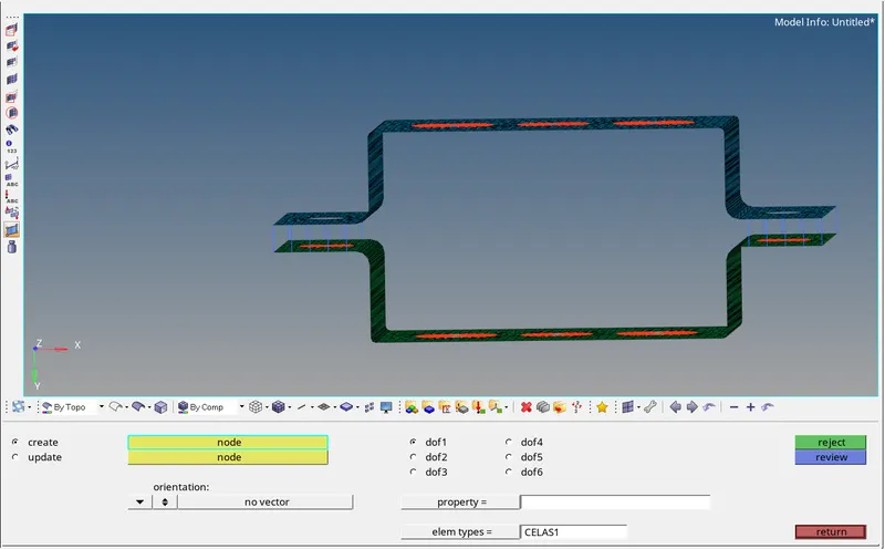
Enable 1D detailed element representation & 2D detailed element representation
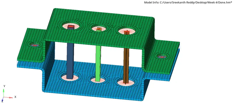
Conclusion:
- Extracted the mid-surface for the given component and meshed to given size.
- Created cross sections for beam, rod and bar and assigned to respective property cards created.
- Deploying the suitable 1D element to the created RBE2 and RBE3 elements as given.
- Detailed element representation of 1D and 2D elements are shown.