Week 4-1D Element Creation Challenge
Objective: To mesh the Parallel bracket component with the size of 5 units and also create 1D elements on the component with the below-mentioned cross-section and degrees of freedom.
a. Rod element: Translational DOF should be Constrained with RBE2 link
Cross-Section: BOX
Dimension a= 12 mm, b= 10 mm
Thickness t= 0.75 mm
b. Beam element: All DOF should be constrained with RBE3 link
Cross-Section: I Section
Dimension a= 8 mm, b= 10 mm, c= 8.5 mm
Thickness t1= 0.75 mm, t2= 0.6 mm, t3= 0.6 mm
c. Bar element: Constrain only x and y DOFs With RBE3 link
Cross-section: X section
Dimension DIM1= 5 mm, DIM3= 10 mm
Thickness DIM2= 1.2 mm, DIM4= 1.2mm
d. & e. Apply the mass of magnitude 10 with the RBE2 link
f. Join the two components with Spring elements
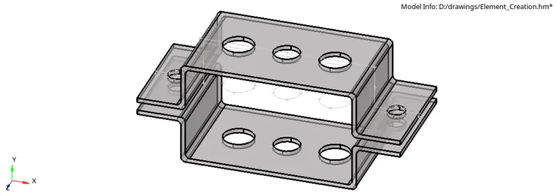
CAD model:
Procedure:
- Import the geometry into the workspace using the "Import Geometry" option from the toolbar.
- Select "Geometry" from the main menu page and choose the "mid surface" option.
- Extract the mid surface by auto midsurface>auto extraction>surfs>extract.
- Hide the parent geometry and leave the extracted mid surface in the workspace.
- For all the holes in the geometry, make a washer split by using the "washer split" command in the "quick edit" options.
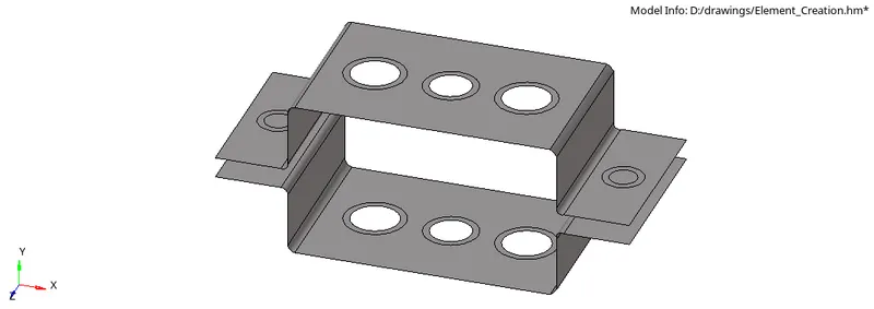
- Select 2D from the main menu page and proceed with the "auto mesh" option to mesh the surface with 5 units.
- Change the number of nodes so as to obtain a proper mesh flow and also to reduce the number of tria elements.
- Now assign a material card and a property card to these brackets and give a thickness of 5mm.
- Using 2D detailed element representation, the meshed model can be seen with a thickness.
- Switch to 1D on the main menu page and choose the rigid option to make an RBE2 link and the RBE3 option for RBE3 links.
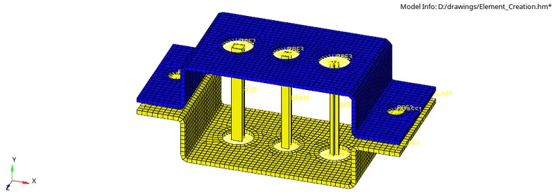
- The spring option is used for creating a spring connection[CELAS1].
- Masses option is used to assign mass at the specified nodes.
- Connections are made as per given DOF's and the type of link[CROD, CBEAM, CBAR] at specified locations.
- Select Hyperbeam>Standard section>section type>create and create the specified shapes.
- Create a property card for each of these sections separately.
- Switch to 1D detailed element representation to view the created sections.
Final Model:

Gdrive link: https://drive.google.com/file/d/1kaR-0befIWaovnW1KPacwm_r9jNdKnIn/view?usp=sharing