Week - 4
1.Control logic of Washing machine:
According to the given conditions, the following chart is prepared:
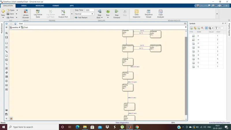
- The system should be activated when there is a power Supply. So with "p" as power supply input i.e., when p=0, the supply is off and there will be no activation inthe system. When the power supply is given to the system, then p=1.
- Accordingly the states are added for on and off of the power supply and are interconnected using the input parameter "p" as shown in the image.
- Once there is a power supply, so the output from the state will be P=1, which is connected to the state Water Supply. There are two states for water supply i.e., on and off. Once the power supply is ensured we need to check the condition whether the water supply is on or off with the input "w". So when both P and w values are 1, the output from the state water supply is on and W=1. If either P or w are not 1, then there is no further state flow from water supply and the output will be W=0
- Once the power and water supply are ensured, the state flows continues towards soaking which is done for 200 secs and the output will be S=1
- After the soaking is done, then the state would move towards washing which is done for 100 secs with output X=1
- Then the state flow move towards rinsing for the next 20 secs with output R=1
- Next comes drying state for 50 secs with output D=1
- Finally there is an end state when process is completed with E=1
- This chart is connected to the input and output ports as shown in below image
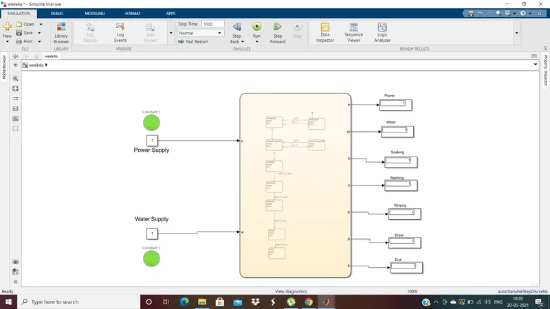
- A constant block for power supply input and another constant block for water supply input are connected along with two lamps to indicate on and off of the respective supplies.A display block is connecetd to all the output of the state flow. The simulation is run for 1000 secs to run the complete cycle of state flow.
- When the power and water supply are given, i.e., the two constant block are given the value zero:
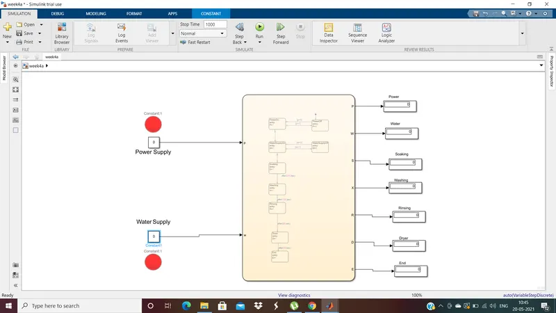
- The two lamps are in red color as there is no supply in both the inputs and all the outputs show 0.
- When the power supply is given and water supply is not given i.e., p=1 and w=0
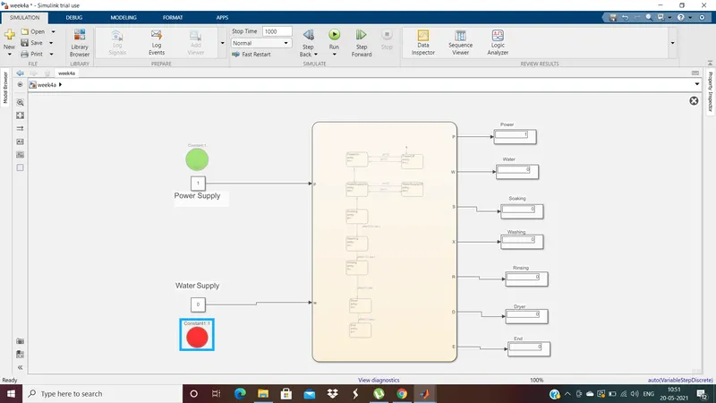
- The power supply lamp is in green and water supply is in red. In the output display we can see only P=1 and the other displays show zero
- When the water supply is given but power supply is off i.e., p=0 and w=1
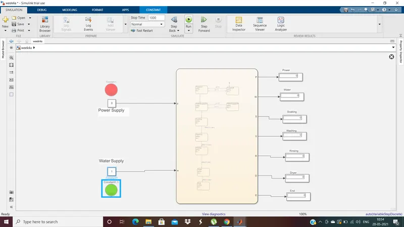
- The power supply lamp is red and water supply is green. All the output show 0 as there is no power supply.
- When both power and water are supplied p=1 and w=1
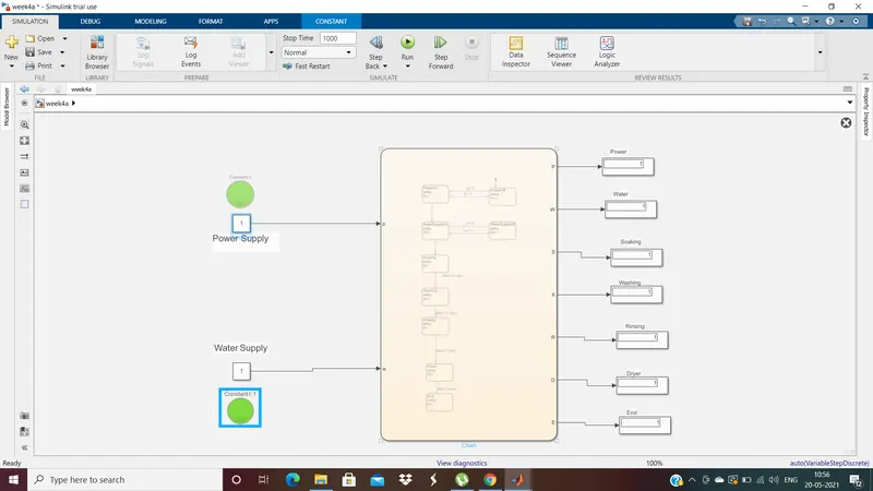
- Both the supply lamps are green and all the outputs display 1 and the washing machine is working as per the state flow.
2. Simulink chart for gear shift logic:
For the given conditions of speed range and gear the chart is prepared as below:
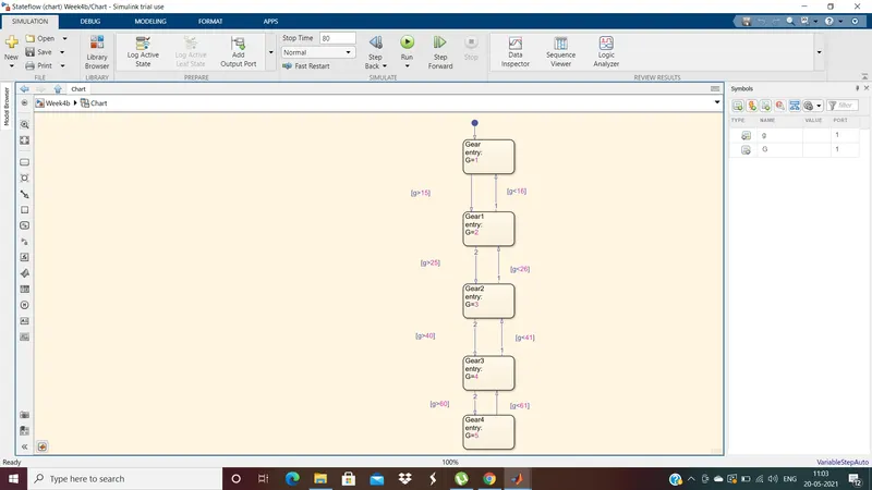
- So according to the given conditions the gear shift value should be changing with the speed range. So the input "g" is going to be the value of the speed.
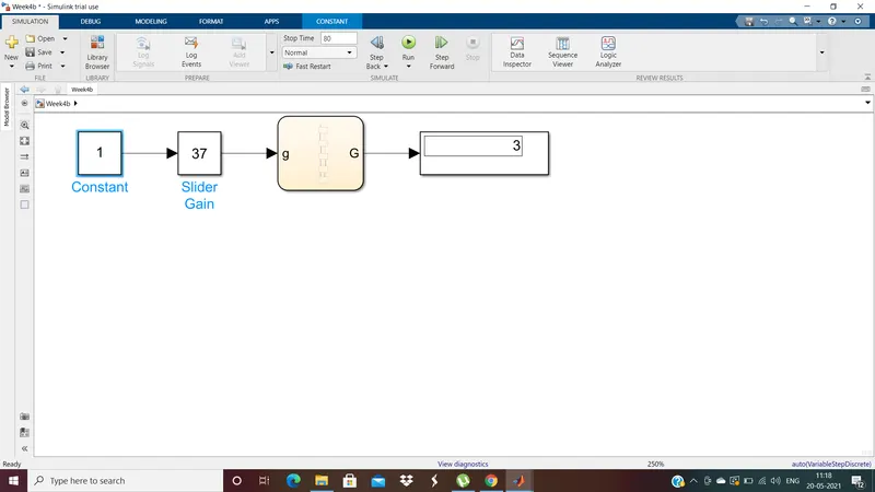
- The chart is connected with a constant and slider gain as input, and a display is connected to note the output.
- The slider gain values can be varied from 0 t0 70 to check all the conditions given. The simulink is run for 80 sec to check the conditions.
- when g value is between 0 and 15, the output value G is 1 from the state Gear
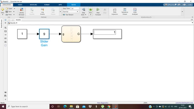
- when g is between 16 and 25, the output of state G is 2 from the state Gear1
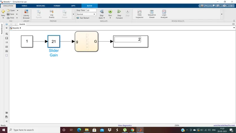
- when g is between 26 and 40, the output of G is 3 from state Gear2
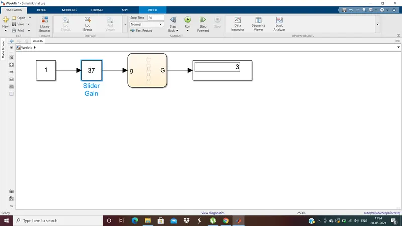
- when g is between 41 and 60, the output of G is 4 from state Gear3
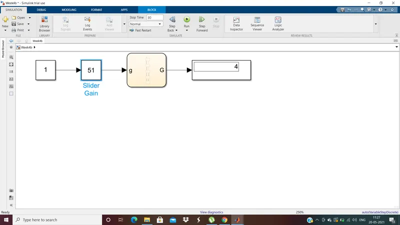
- when g is more than 61, the output of G is 5 from state Gear4
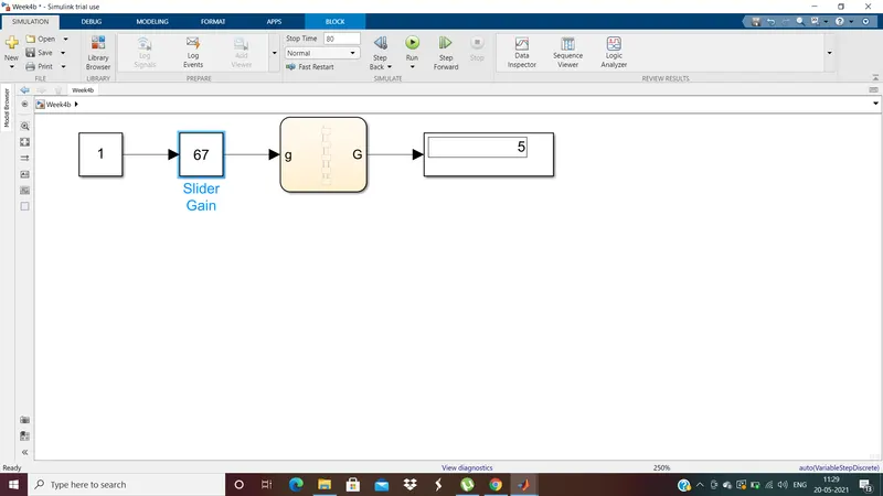
- Thus gear shift chart is designed as per given conditions.