Week -2
1.Simulink model of Doorbell:
The below model shows a doorbell using solenoid block
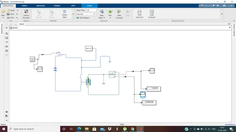
The simulink model consists of the following blocks:
Solenoid
Ideal translational motion sensor
Pulse Generator
Switch
Battery
Solver Configuration
Electrical reference
Mechanical reference
scope
display
Simulink-PS convertor
PS-Simulink convertor
Connections:
- As per the given condition, the switch should be closed for two seconds, so a pulse generator is connected to the switch to close the switch after every 2 seconds time interval. It is not possible to connect a switch directly to a pulse generator because the pulse generator gives a simulink signal and the switch needs a physical signal. So a simulink-PS convertor is connected between the pulse generator and switch.
- The switch is connected to a battery, which is connected to the inductance part of the solenoid and closed loop is formed by connecting the other end of the solenoid to the switch, so when the switch if closed there would be closed loop with switch, batter, and solenoid.
- Also an electrical reference and a solver configuration are add to this loop as shown in the image.
- The mechanical part of the solenoid is connected to a Ideal transitional motion sensor
- A mechanical reference and scope and displays are connected to notice the output velocity and position.
Working:
- The switch is operated using the pulse generator where a pulse is generated for every 2 seconds as shown below
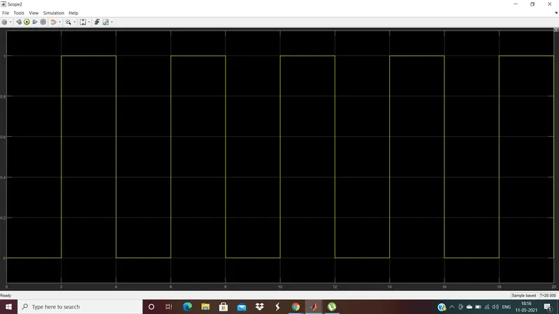 .
. - The first 2 seconds when there is no pulse from the generator, the switch will be in off condition and that forms a loop and no current would pass through the inductance of the solenoid.
- As there is no current passing through the inductance the magnetic field is formed for the motion between the R and C ports, so there will be zero velocity and no change in the position
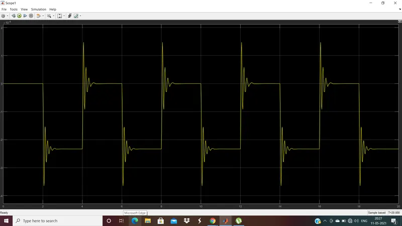
- Position scope:
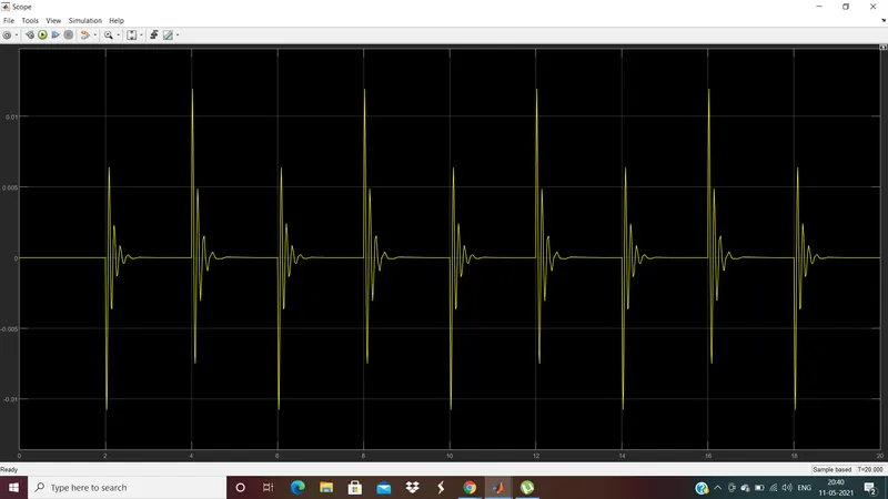
- Velocity scope:
- For the next 2 seconds i.e., from 2 to 4 seconds, the pulse is generated and the switch is closed and form a closed circut with electrical part of the solenoid.
- As it is a closed loop with a battery, the voltage is applied and current passes through the inductance and due the excitation formed there will be a change in position(X) of the port. where X is the initial air gap or stroke of the solenoid.
- The change in the position can be seen in the position scope and the value of X is zero intially, but when the switch is closed from 2 to 4 seconds there is a sudden change in the position which ocvillated for few milliseconds and then a fixed value till the end od 4 seconds.
- The velocity scope can also be seen that there is a spike in velocity and then ocillating for few milli seconds whenever there is a change in the position of the switch. and then the oscillations come to zero and remains there till the next action of the switch. All the velocity occurs due to the spring action in the solenoid.
- As the positive side of the battery is connected to the negative port of the solenoid, that creates a negative force which a pull-in force. So we get the position displacement as a negative value.
- This process continues for very 2 seconds and the cycle goes on for the time specified(20 seconds here)
- The position and velocity values values are display on the respective display blocks at the end of the simulation.
Conclusion:
For the above model, whenever there is an input signal pulse the switch closes and a magnetic force is formed due the rated cuurent and rated voltage around inductance. Due to this magnetic force there is a displacement in the mecganical part i.e., between the port R and C. Due to this displacement the and velocity in the mechanical part, this solenoid hits the bell and that rings for every 2 seconds according to the pulse generated.
2. Use thermistor to sense the temperature change:
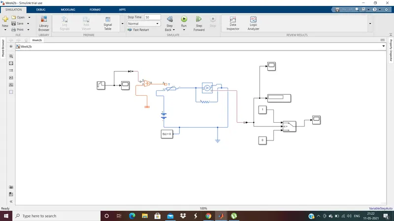
The model consists of the blocks:
- Thermistor(to sense the temperature)
- Controlled temperature source(to balance the temperature)
- Repeating sequence stair
- Resistor
- Votage sensor
- Solver configuration
- Battery
- Switch
- Electrical reference
- Mechanical refernce
- Scope
- Display
- Ps-Simulink convertor
- Simulink-PS convertor
Connections:
- Thermistors change the resistance when there is a change in the temeprature, it is like a temperature dependant resistance. It is connected in a circuit to balance the temperature. So in the abobe model the thermal port of the thermistor is connected to the Controlled temperature source, this is a ideal thermal energy source which can maintain a constant temperature even though there in a increase in the heat
- The resistance part of the thermistor is connected to battery and resistor, which is again connected to the other port of the resistance in thermistor as shown in the above circuit.
- For a thermistor according to the parameter in default it is necessary to have a voltage divider connected to it. Resistor is a generally a basic voltage divider. that is why we have connected a resistor in the circuit along with thermistor.
- A solver configuration and a electrical reference are also connected in the circuit.
- A voltage sensor is attached across the resistor, to have a track of the voltage across the voltage didvider. The votage sensor is connected to a Switch through a PS- Simulink covertor, a scope to track the changes in the voltage according to the temperature and display to display the final voltage.
- The three port is connected to the voltage sensor, The signal passes through the first port when the condition in the second port is satisfied else it will pass through the third port. So the switch acts a basic if-else block with a condition given. So two constant blocks are connected for the 1st and 3rd port and the values of 1 and 0 are given respectively, to open and close the switch.
- So to give the condition in the port 2, we need to the check the voltage drop across the resistor when a temperature of 25 degrees celsius. So the temperature in celsius is first converted to kelvin i.e., 25+273= 298K.
- This value 298 is given as input to the controlled temperatue source using a contant block through a simulink-Ps convertor and then run the simulation. The connections are shown in the below image:
-
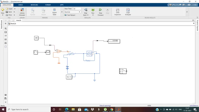
- The voltage that is displayed is 0.01189, so this value is given at the 2nd port of the switch as condition. So when the temeprature increases, the voltage drop across the resistance also increases and the switch will be closed when the voltage is greater or equal to 0.01189 and the switch will be opened when the voltage is less than the specified value.
- So, once the voltagde across the resistance is known for the given temperature, the constant block which is connecetd to the controlled source temperatue is removed and repesating sequence stair is connected through the simulink-PS convertor. The values in this block are given as shown below
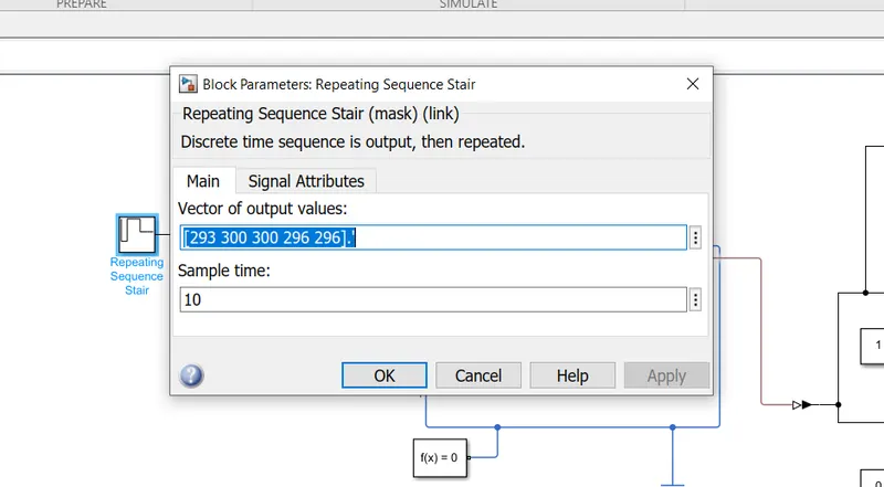
- The values are 293, 300, 300, 296, 296. So in the given question the temperature should be 20 degrees celsius in first 10 seconds, 27 degrees celsius for nect 20 seconds and 23 degrees celsius for next 20 seconds. so a sampling time of 10 seconds is taken and the values the given twice when that lasts for 20 seconds. The temperatures are converted to respective values in kelvin.
- Finally a scope is connected to the switch, to track the on and off conditiond of the switch.
Working:
- From the repeating sequence stair, the temperature values are gieven as an input to the controlled Temperature source and to the thermistor.
- The scope of the repeating sequence stair:

- for the first 10 seconds, the value is 293K
- Then the voltage drop across the resistor is calculated by the voltage sensor and that is fed to the switch, The voltage scope can be seen below
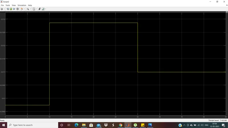
- The voltage across the resistor for the first 10 seconds in less than the value 0.01189i.e., voltage at 25C , so the condition in the switch is not satisfied and the signal passes through the 3rd port of the switch and the switch remains opened.
- The switch scope can be seen below:
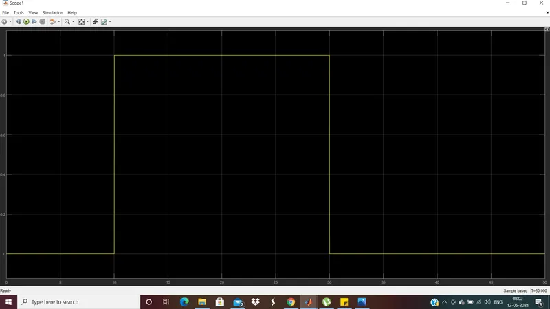
- For the next 20 seconds, the repeating sequence stair gives avalue of 300K, which is greater than the 298K(25C), the temperature at which the switch should close.
- So, the voltage at this temperature across the resistor is greater than 0.01189V, so it satisfies the condition of the switch and the signal from the port1 passes and the switch gets closed during this time interval.
- In the last 20 seconds, when the value in the repeating sequence stair is 296K, which is less than 298K, the voltage drop across the resistor would be less than 0.01189V, so it does not satisfy the condition of the 2nd port of the switch and the switch opens.
- So, the model works according to the condition given, i.e., the switch should be closed when the temperatue is greater than or equal to 298K and opened if the temperature is less than 298K.
- The diplay connected to the voltage sensor shows a value of 0.01099V at the end of simulation time 50seconds i.e., the voltage across the resistor at 296K.