Project
Aim: To run the simulation of a Baja ATV and see the characteristics of the vehicle.
Description:
An ATV is a small vehicle like a simple car, which are generally used in races, deserts, forests or mountains. It is a simple vehicle also light utility vehicle. It is a vehicle that travels on low-pressure tires, with a seat that is straddled by the operator, along with handlebars for steering control. As the name implies, it is designed to handle a wider variety of terrain than most other vehicles.
The simulink model of a ATV is shown below:
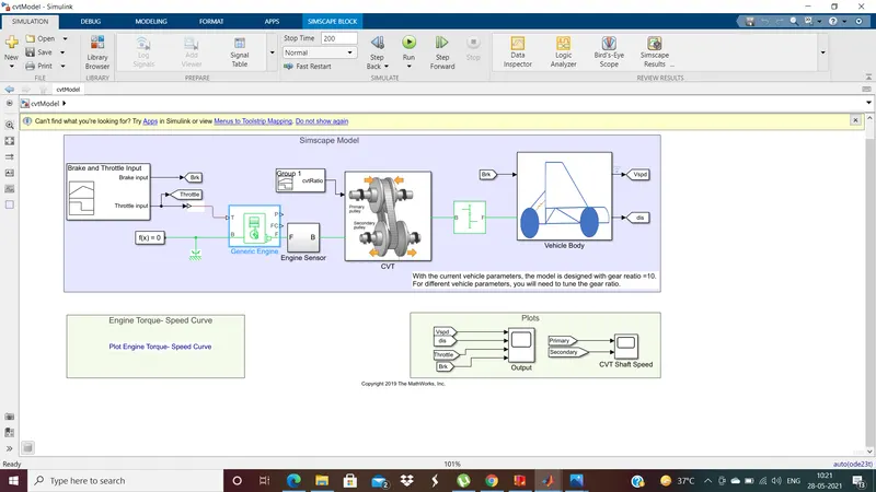
Let's first see the connections and building of this model. The three main components of this model are:
1. Generic Engine:
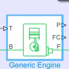
- The generic engine block represents a general internal combustion engine. The block is a suitable generic engine for spark ignition and diesel.
- The engine basically uses the throttle as input from the port "T", which is given using the signal builder. The engine converts the throttle input into angular velocity from the port "F", which is called the crank shaft. The angular velocity and angular displacement are plotted using the Engine sensor connected to the port "F" of the engine.
- The generic engine uses a programmed relationship between throttle and speed that is modulated by the input throttle signal.
- The torque speed curve is fed to the engine using GRABIT file exchange, where we have a curve of a typical BAJA engine characteristics through creation of column vectors in MATLAB. The torque- speed curve is as shown below.
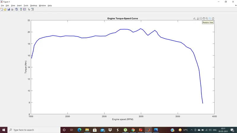
- So the maximum speed that is obtained from a BAJA vehicle is around 3840 RPM, which can be seen in the curve.
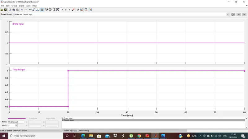
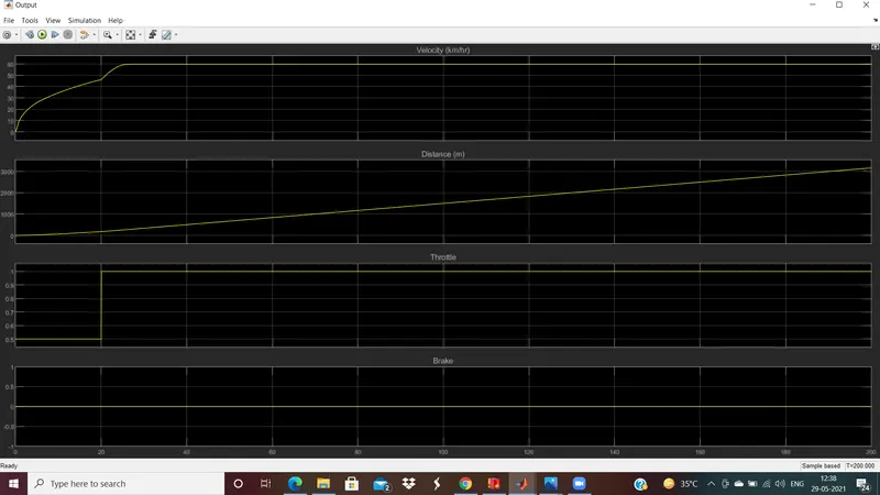
- Initially the Throttle and Brake are input are given to the Generic engine with brake=0 and throttle=0.5 values using a signal builder.
- Let us set the value of throttle to 0.5 for the first 20 seconds and to 1 for the remaining time, leaving the brake value at zero.
- The prot "B" of the engine is connected to mecganical rotational referrence and solver configuration.
2. CVT(Continously variable Transmission)
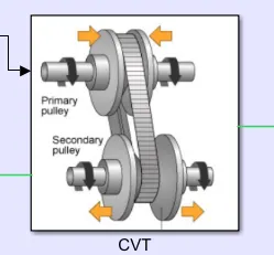
- The crankshaft of the engine is connected to this CVT.
- The CVT is generally used to get a variable gear ratio instead of a fixed one.
- CVT consists of 2 pulleys, primary and secondary, which are connected to each other using a steel belt.
- It is used to transmit power from input shaft connected to the primary pulley to the output shaft connected to the secondary pulley using the belt.
- The gear ratio can be adjusted continously according to the required output power. this possible by adjusting the pulley sheaves distance.
- When the radius of primary pulley Rp > Rs i.e., radius of secondary pulley, the speed of the vehicle can be reduced. When Rp<Rs, the speed is increased.
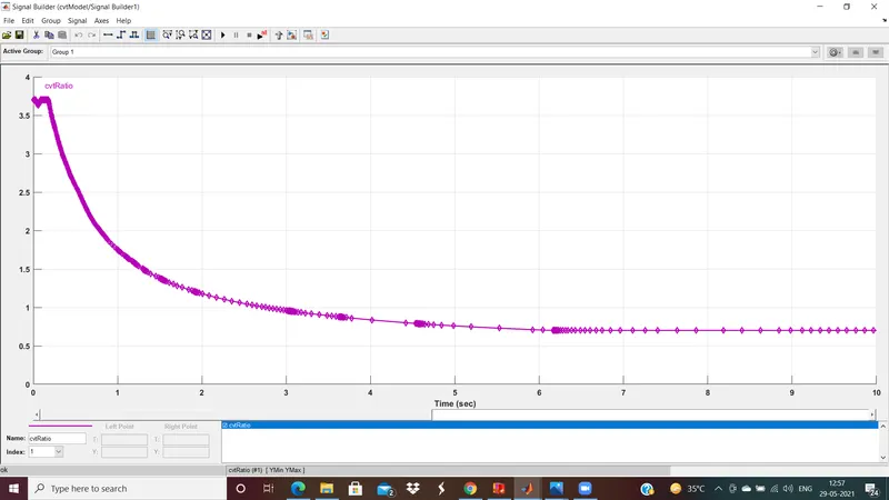
- The gear ratio can be calculated as Rp/ Rs and it gets adjusted according to the speed required.
- CVT block diagram representation:
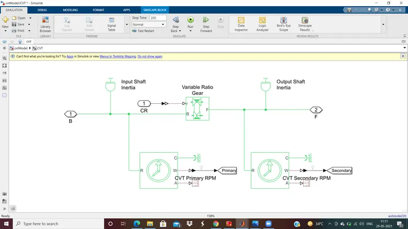
- From the above image we can observe a variable ratio gear block, where the gera ratio can be varied using a gear ratio input, which is given using a signal builder through port R.
- The primary pulley and secondary pulley are represented by the input and output shaft inertia respectively.
- The primary and secondary pulleys rotation are calculated using the sensors placed at the shafts and respective GOTO blocks are connecetd to track the angular velocities.
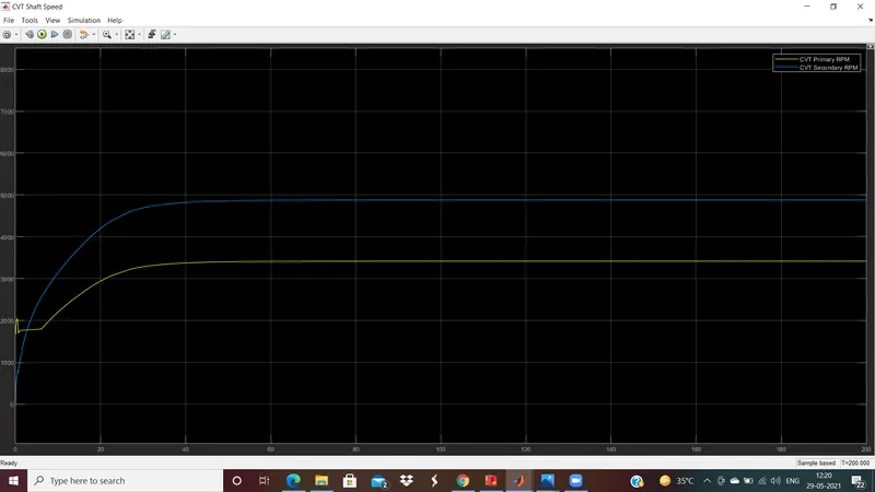
- The primary and secondary pulleys velocities are tracked with a scope as shown below.
3. Vehicle Body:
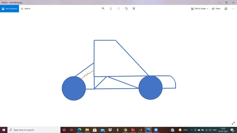
- Simulink model of vehicle body:
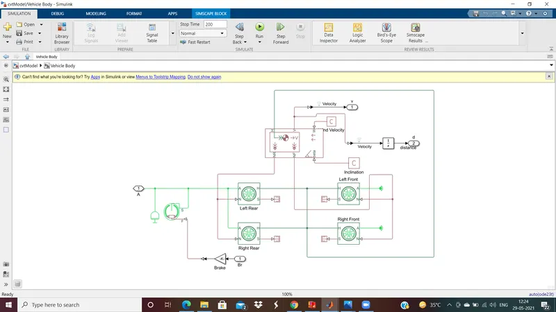
- The simulink model is designed in a way that two wheels are connected to a single axle, so there would be 2 axles for the 4 wheels.
- The vehicle body consists of weight of the body, road incline, wind velocity and the weight is distributed evenly over the axles.
- The 4 wheels are connected to a Double shoe brake block, this block represents a fictional brake with two pivoted rigid shoes that press against the rotating drum to produce a braking action.
- Double shoe brakes provide high braking torque with small actuator deflections in applications.
Let's see the final speed for the given brake and throttle input:
CVT gear ratio signal:
Primary and secondary pulleys speed:
Lets change the CVT gear ratio in the signal builder:
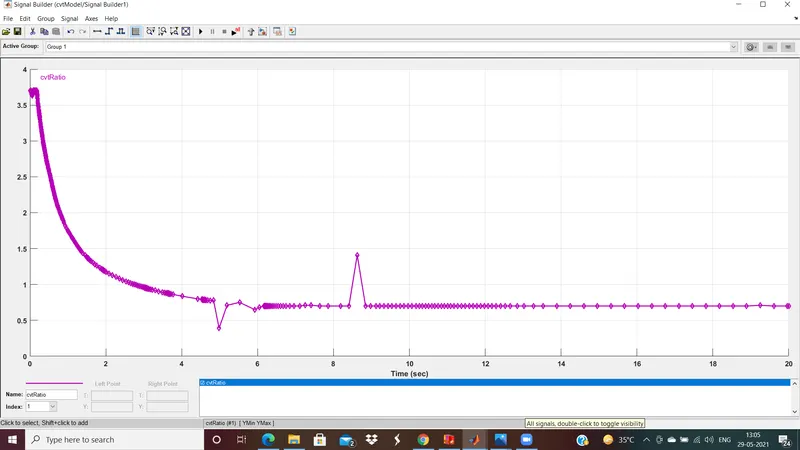
Now observe the changes in primary and secondary pulleys speed:
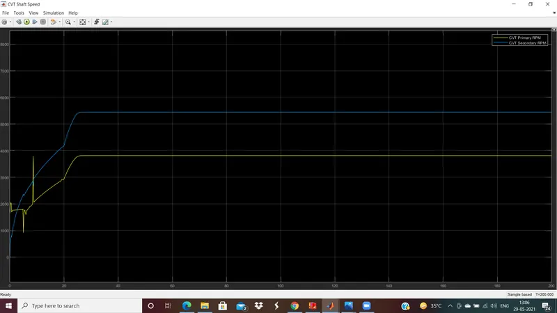
When the CVT gear ratio is less than1, the primary speed is less than secondary speed and the vice versa happens when the gear ratio is greater than 1.
Let's stuidy this same model with a Dashboard:
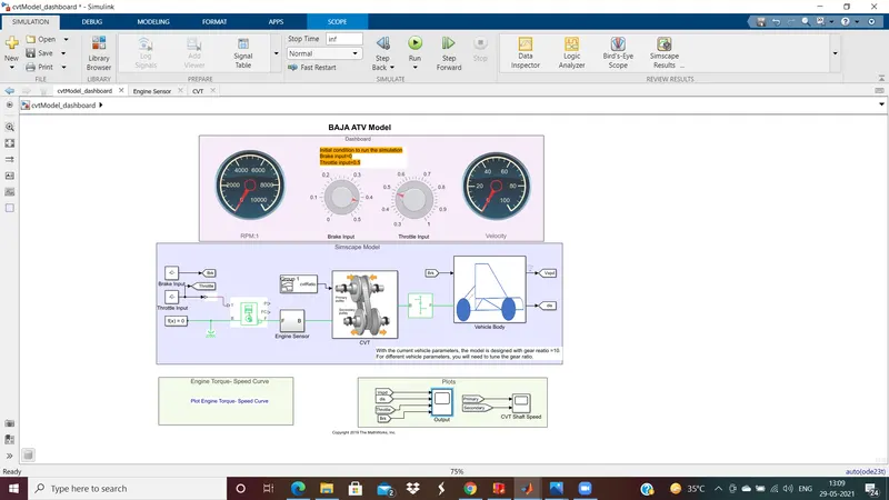
The same Baja ATV model can be seen but with a dashboard placed to track the rpm and speed of the vehicle.
We can change the brake and throttle from the knobs present at the top of the model while running the simulation.
Let's change the values of brake and throttle through the knob and record the changes in velocity of the vehicle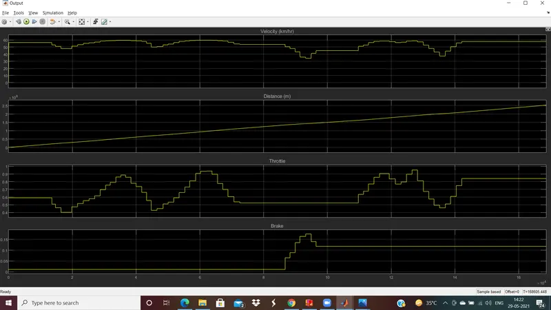 .
.
The simulation runs for infinite time, so we can change the brake and throttle, to plot the velocity changes as shown above.
This complete ATV runs in an open loop, as a signal builder is connected for the gear ratio.
Now let's see the Baja ATV vehicle which runs runs in a closed loop i.e.,
Conclusion:
The output velocity characteristics of a Baja ATV vehicle is observed under different conditions of CVT. The condition of ATV can be studied by focusing on the given two conditions of CVT i.e., in open loop and closed loop using lookup table