Week - 4
Q1.
1.
2.
3.
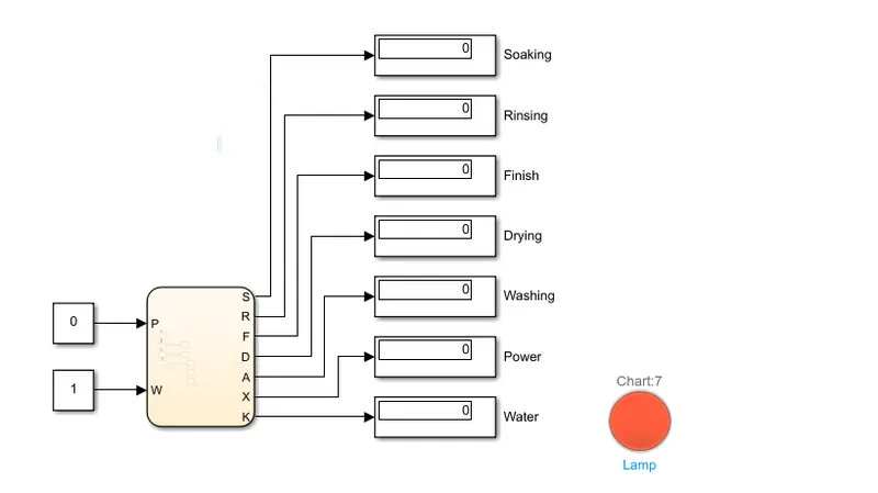
A) As per the question, image 1 showing when power supply is not available then machine is not working even if watersupply is available. Red LED sghowing default state that if power is not available then loop will break and it comes out of flow chart.
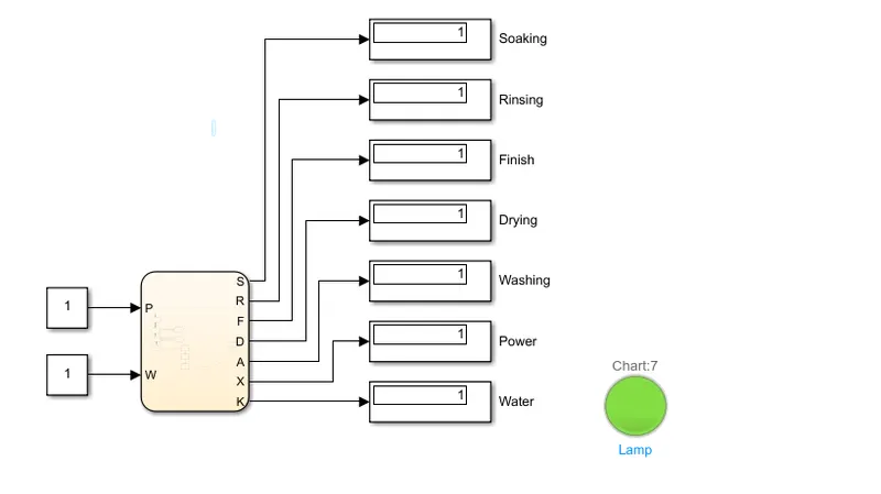
B) Image 2 is showing when water supply and powersupply is available then machine is running and doing tasks as per requirements.
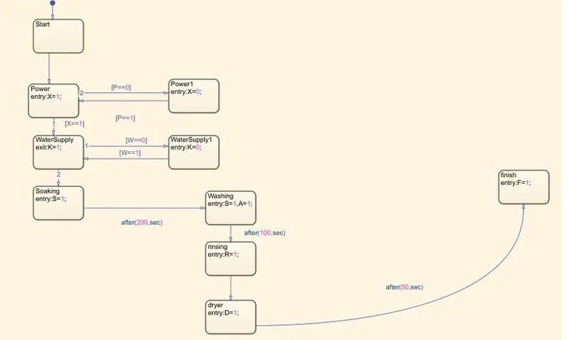
C)Image3 is showing State machine flow chart.
Conclusion: It has been concluded that condition has been simulated as per need.
Q2.
1.
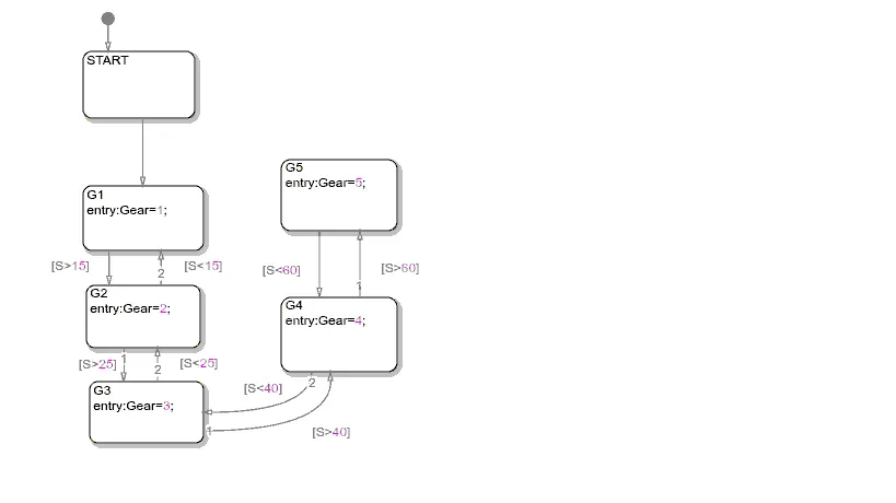
2.
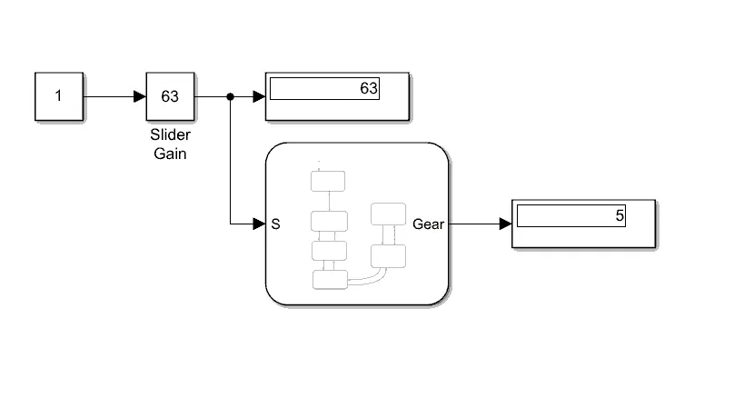
A) As shown in Image1 , used slider gain with constant of to change values during simulation as asked.
B) Image2 is showing flow chart in which all conditions are being used. Here S is used as input and Gear which acts as output is used for displaying which Gear Shift System is working.