Week -2
Q1:
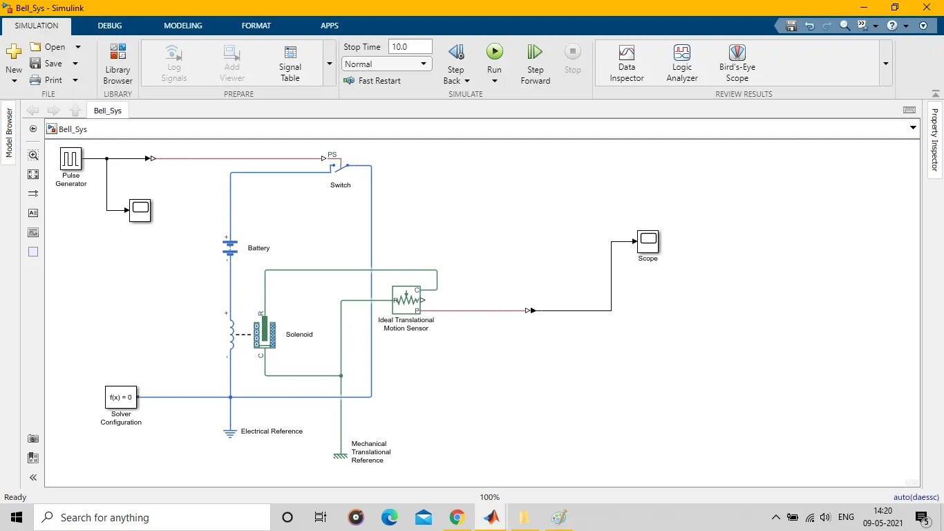
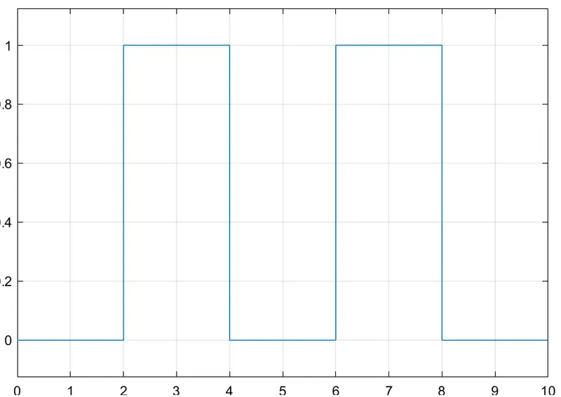
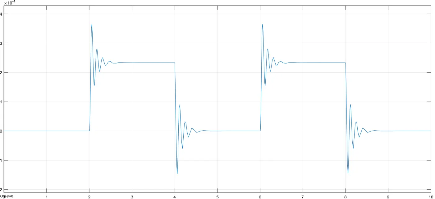
- In the above simulink diagram, pulse generator is used which genrates signal to overcome threshold value for switch so that switch can be closed. As shown in 2nd image i.e., graph showing that it has apmlitude of 1, phase of 2s and its period is 4s and width is 2s. In swith, used threshold value is 0.5. So, after delay of 2s it will close the switch and battery as used will be connected. So, it will excite coil of solenoid and pulls plunger towards the terminal C, since C is used as mechanical referrence with R terminal in Ideal transational sensor. So, there will be displacement of of positive value as shown in graph 3. And then it oscillates to and fro which generates oscillation as shown in the graph above. Since, signal applied by pulse generator is of 2s, so switch will be closed for 2s and then solenoid will be excited for same time. Plunger will maintain its position for2s. And again when it will be released as switch will be open, solenoid will loose flux and again come to its orignal again after oscillations.
- As in Image 2 and Image 3, it can be realted. It is showing positive displacement as I have used R as mechanical translational referrence in Ideal Translational Motion Sensor.
Q2.
1. 
2. 
3.
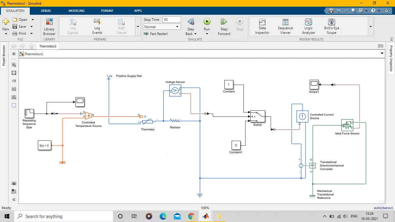
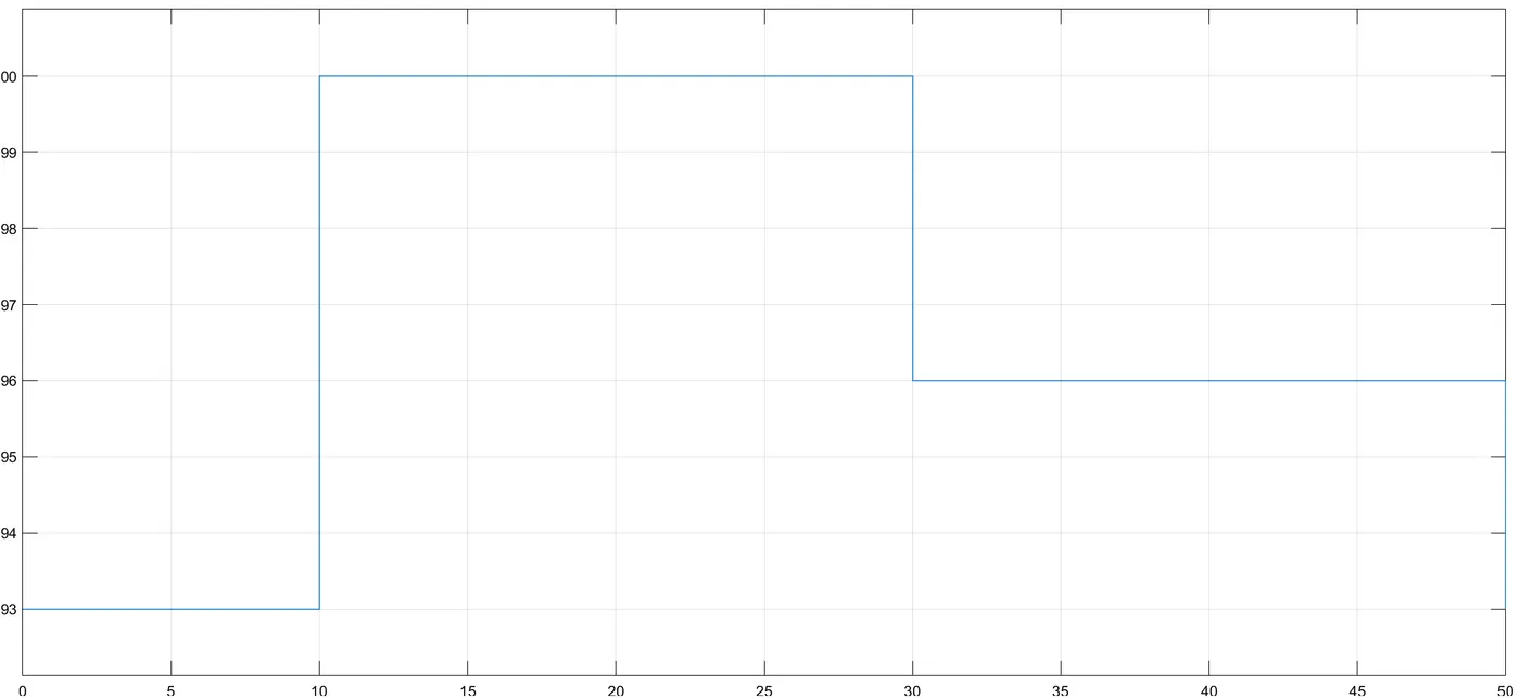
A.In the Q2 as we have asked to implement some conditions. So, in Image 1 showing simulink model, in this repeating sequence stair is used which generates signal as duration of 10s, 20s, 20s having amplitude of 293, 300 and 296 as converted into kelvin respectively. And graph can be seen in Image 2. Then from controlled temprature source which generates respective temprature value, then to thermistor which generates volatge difference with help of volatge divider as seen in model, resistor is connected with it. The circuit is having biasing voltage of 12V and a voltage sensor is connected in parallel with resistor which senses voltage and can be given by formula
Vr=Vin*(Vr/Vr+resistance of thermistor(at diff temprature))
B.Output signal from voltage sensor is given to switch which has threshold value on which switch operates. Two terminals of switch is connected to two constants 1 and 0 which denotes ON and OFF condition respectively.
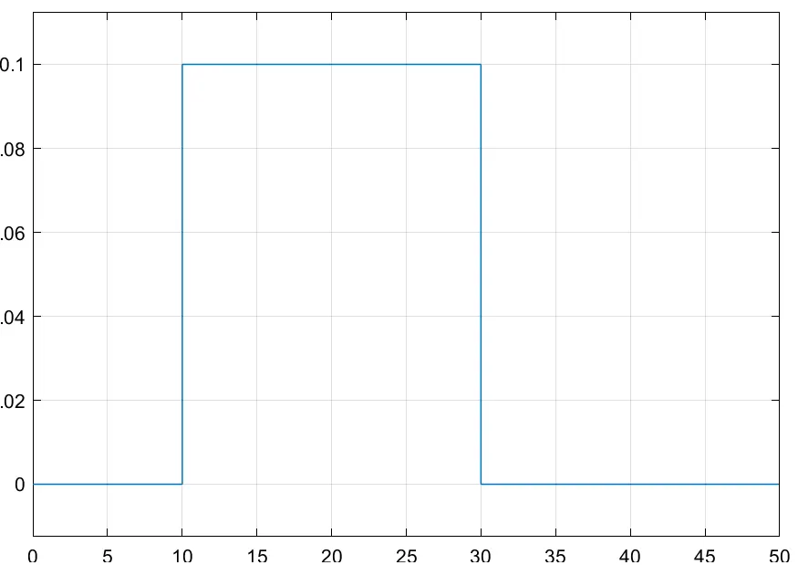
C. Output from switch is fed to Ideal controlled current source which generates current when signal is applied to control input port of current source. And output of current source is applied to translational electromechanical converter which convert input current value to corresponding force value which is sensed by Ideal force sensor and Ideal force sensor output is given to scope whoose output is shown in Image3, which denotes movement of FAN as per the question.
OBSERVATION: From the Image 3, it can be observed that force is Zero until 10s and then Force is increased for 10s to 30s as temprature is greater that 25C and again fan is off as after 30s temperature is reduced to 23C. So, it can be observed that conditions are fullfield according to question