Week - 4
1.
Aim:-
- To implement control logic of washing machine using stateflow as per given conditions.
- If the power supply is there then the system will move to next step else give an error.
- In the next step water supply is to be checked. If the water supply is there then the process will move to next step else stop the process and give indications.
- After the water is filled up then the soaking process will take place for 200seconds.
- After the soaking is done then the washing will take place for 100 seconds.
- After the washing process the water will be drained out in the rinzing process for 20 seconds.
- After the rinzing drying of the clothes wil take place for 50seconds.
- After 50 seconds the led will light up showing the full process of washing is complete.
Theory:-
In this model we have to implement the condition for the working principle of the washing machine. At first the power input is to be checked. If power input is given then the next step will be the filling of water in the washing machine. So to fill up the water we need to check for water input connection. If the water input connection is not connected then the process will stop there and indicate it via led bulb. If the water input is given then the machine will enter the next process which is soaking of the clothes for 200 seconds. After the soaking is done then Washing will take place for 100 seconds. After the washing of the clothes the water is drained out for 20 seconds. The process of draining out of water is called the rinzing process. Then the drying of the clothes will take place for 50 seconds in the drying process and after the drying process an led will light up showing that the all the process are done. We have also connected each process with an led indicator. So that one by one the process will get completed will be indicated by the led. In case of an error or problem in any one of the process will also be indicated by the led.
Control Logic of the Washing Machine:-
We have used the chart block to define the control logic which will govern the process of washing machine. Two input ports are created for the power and water input. And 7 output ports are created for displaying the output for each process. The port will be determined by "Symbols Pane" either Input or Output for this model.
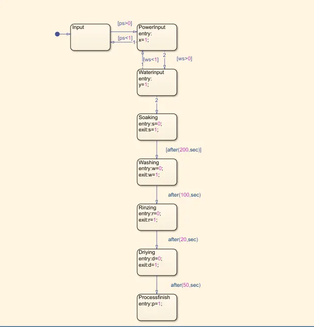
Control Logic for Washing Machine
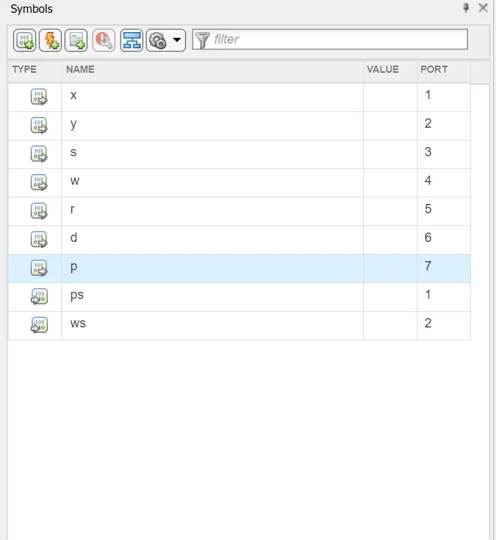
Determine the Input and the Output port
Final Model:-
After creating the Control Logic for the working of washing machine and creating the input and the output ports. We give the input by using a constant for the power and water input. The outputs for each process is connected to the display and led. We also have to set the stop time based on the total time given to the control logic for all the process. So we have to set the time approx to 500 seconds.
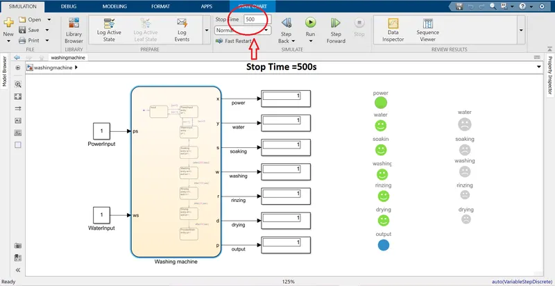
Model of Washing Machine
2.
Aim:-
- To make a simulink chat for the "gear shift" logic on the given condition.
speedrange(km/hr) gear
0 to 15 1
16 to 25 2
26 to 40 3
41 to 60 4
above 60 5
- For varying speed we will use a slider gain.
Theory:-
At first we define the control logic for the gear shift variation with respect to speed. At first we give the condition for speed is less than or equalto 0 then the gear position will be neutral. Then we give a variation in speed from (0 to 15) at which we give the gear change to 1. In the second condition we increase the speed range from (16 to 25) and the gear shift will be to 2. If the speed goes down to less than or equalto 15 than again the gear will change back to gear 1. In the same manner we give the conditions for (26 to 40) , (41 to 60) and above 60 and the gear shift will be from 3,4 and 5 with respect to speed. There are 1 input port to enter the speed and 1 output port to determine the gearshift. The input port is connected to the slider gain to create the varring speed. we can set the minimum and maximum speed in the slider gain. And we also connected a led bulb to the slider gain to indicate that speed input is there.
Control Logic:-
We define the governing logic for the gear system in a chart based on the conditions given in the question. There will be two ports 1 input and 1 output. The speed will be the input port and the gear shift will be output port. The port will be determined by "Symbols Pane" either Input or Output for this model.
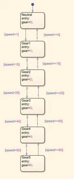
Control Logic
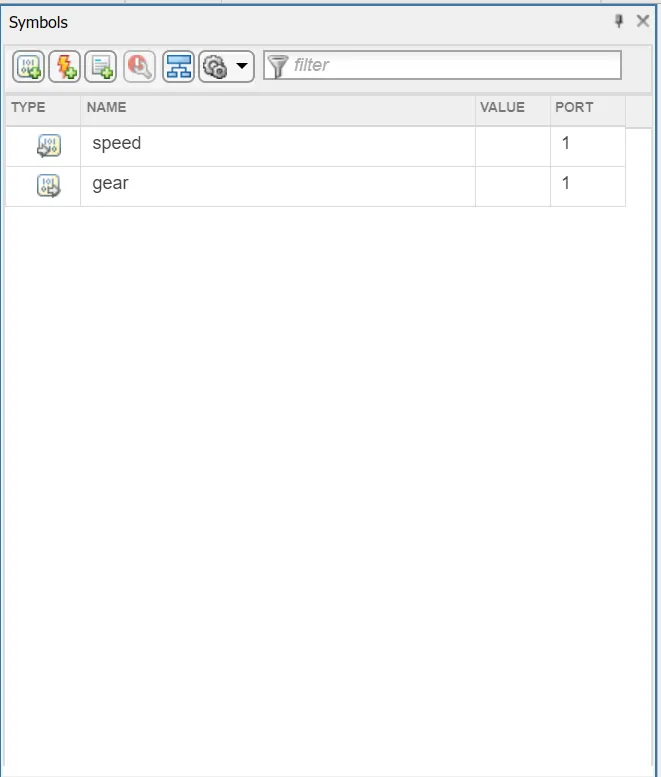
Input and Output port
Final Model:-
After creating the control logic we connect the slider gain to the speed input of the chart and a display to the gear output of the chart. We also connect a constant to the slider gain with a value 1. And a led bulb is connected to the slider gain to determine the speed.
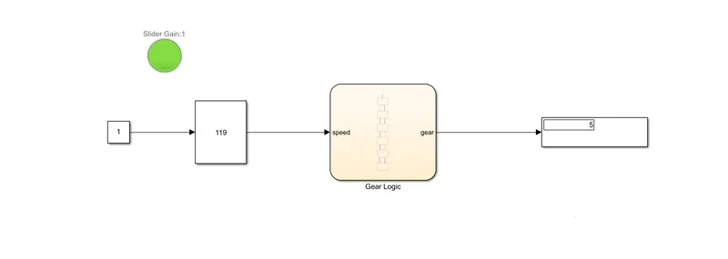
Final Model