Week - 4
AIM:
To apply the control logic of washing machine using state flow for the given sequence requirements.
To make a simulink chart for the Gear-shifting under the given conditions.
PROCEDURE:
Given Data:
i) The sequence of control logic of Washing Machine is as:
* The system gets activated if the power supply is available
* Stop the process and indicate RED if the water supply is not available
* Soaking time=200s, Washing time=100s
* Rinsing=20s, Dryer=50s
After all the process, turn on the finished LED
ii) Making the simulink chart for gear as required:
0-15 km/h = 1st gear
16-25 km/h = 2nd gear
26-40 km/h = 3rd gear
41-60 km/h = 4th gear
61-above = 5th gear
Give the speed indication is running and display the gear number
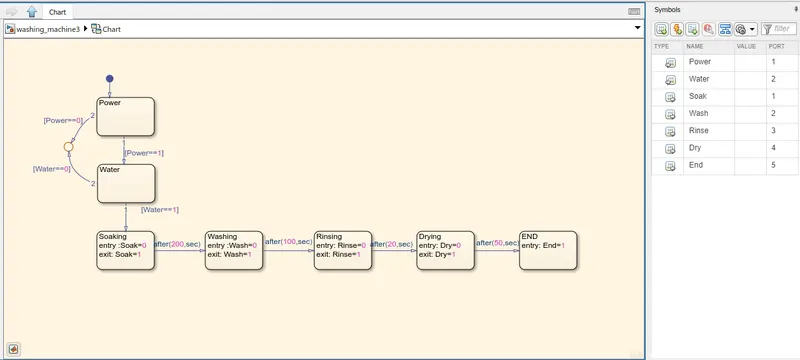
Figure-1(Chart and symbol assigning)
Method:
* Switch is used to control the power supply
* Assign the blocks as required.
* If POWER==1, the input is directed to the next water block. If POWER==0, the input is directed to the junction.
* Next state is WATER. If WATER==1, it is directed to next stage. If WATER==0, it is directed to the junction.
* Next is SOAKING, the entry is given as 0, while exit is LED is made to glow
* After 200 seconds, It is directed to Washing state, After 100 seconds, it is directed rinsing, after 20 seconds, it is directed to drying state, and after 50 seconds, it is directed to end state.
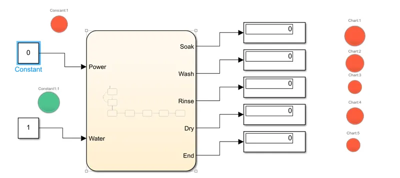
Figure-2: (Water supply is given, but the power supply is not given, showing the system is activated. The LED is RED in colour, indicates the state of power supply).
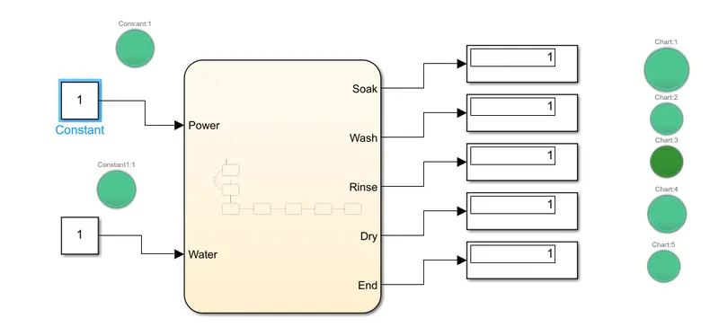
Figure-3: (all the process has been done and the LED is running).
ii) Make a simulink model for GEAR-SHIFT
Given Data:
0-15 km/h = 1st gear
16-25 km/h = 2nd gear
26-40 km/h = 3rd gear
41-60 km/h = 4th gear
61-above = 5th gear
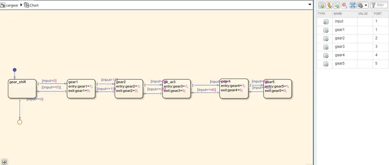
figure-4(the chart model of input and assigning gear value).
Method:
* The inputs are varied by the user during the run-time and is connected to the constant block via Slider block.
* The varying inputs are given to the chart from the constant blocks.
* State blocks are used to get a conditioned state flow.
* The input values are connected to the conditon, Gear>0 proceeds the next state and gear==0, it ends the flow to the junction.
* If gear>0,it moves to the gear1, and when the input crosses 15, It moves to the next state. i.e., gear>15, moves to the next state.
* If Gear>15, it moves gear2 state, and if gear>25, it moves to gear3 state.
* If gear>40, it moves gear4 state, and if gear>60, it moves to gear5 state.
* And a lamp is connected on each states, and so the lamp will glow on their respective gears and all other lamps will be off.
* A Display block is connected to get the value either 0 and 1, denoting that the lamp is in native state.
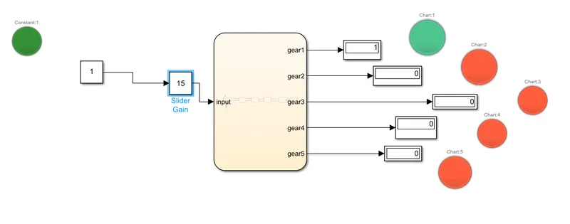
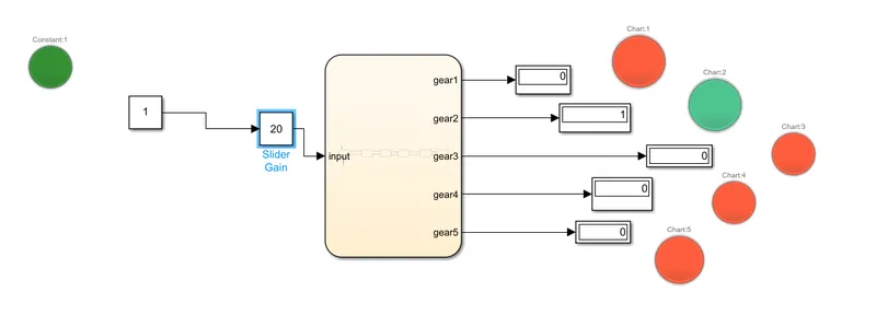
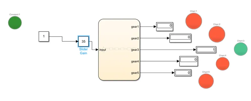
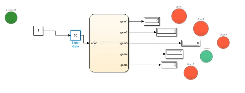
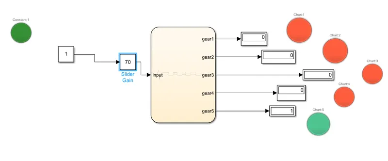
from these figures, these show that the GREEN light is glowing according to the gears which are active.
LEARNING OUTCOMES:
* Working of slider
* Working of Stateflow
Results:
*Applying the control logic of washing machine using state flow for the given sequence requirements and making a simulink chart for the Gear-shifting under the given conditions, has done in SIMULINK software