Week 4.1: Project Steady state simulation of flow over a throttle body
Objective:
Simulating flow over a throttle body in steady state & transient condition. The throttle remain steady in steady state while position will chnage in transient condition.
Write a detailed report.
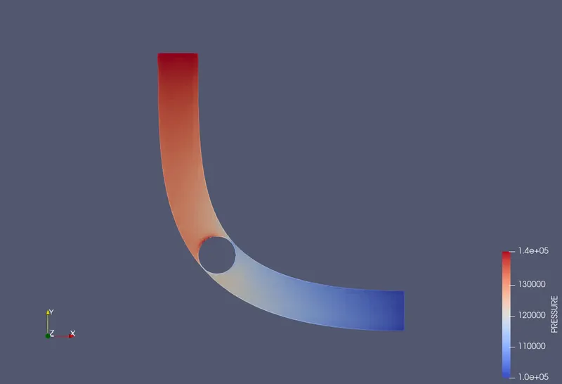
Post process the results and show pressure and velocity contours.
Show the mesh (i.e surface with edges)
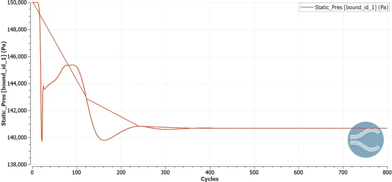
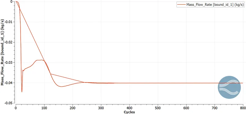
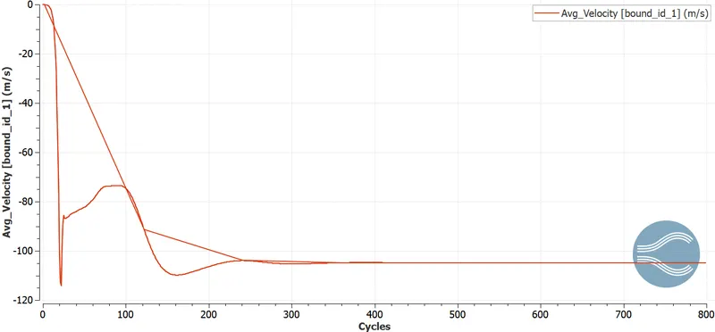
Show the plots for pressure, velocity, mass flow rate and total cell count.
Answer:
Received geometry
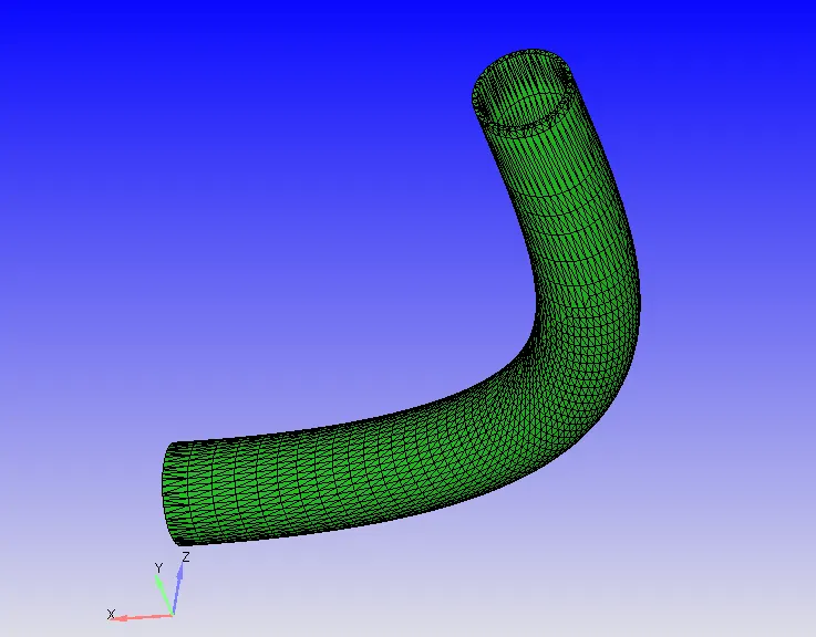
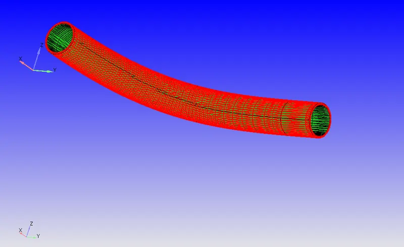
As thickness has no specific importance in this simulation, it is going to be deleted.
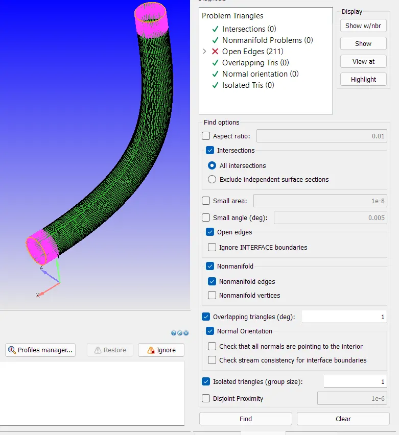
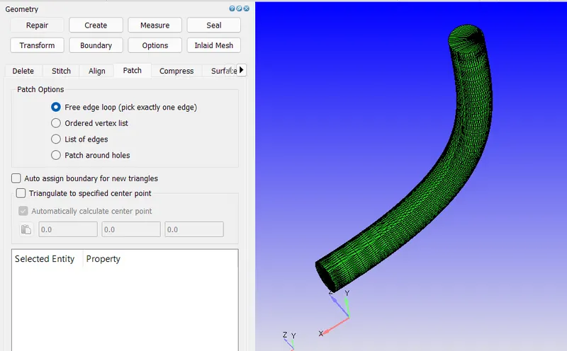
The diagnostic has beed performed. 211 open edges was found, highighted in the pink.
To solve this patches were created to make geometry close.
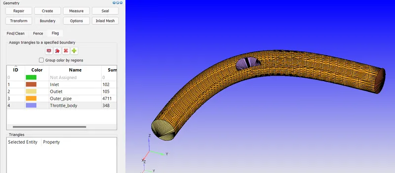
Respective boundary name has been assigned.
Model converted for meter unit system
Scaling factor = 0.001
Simulation case setup
Simulation type = Time based
Material = Air
Gas Simulation = Default options
Globla transport parameters = Default options
Solver = Steady State
Simulation Time parameters
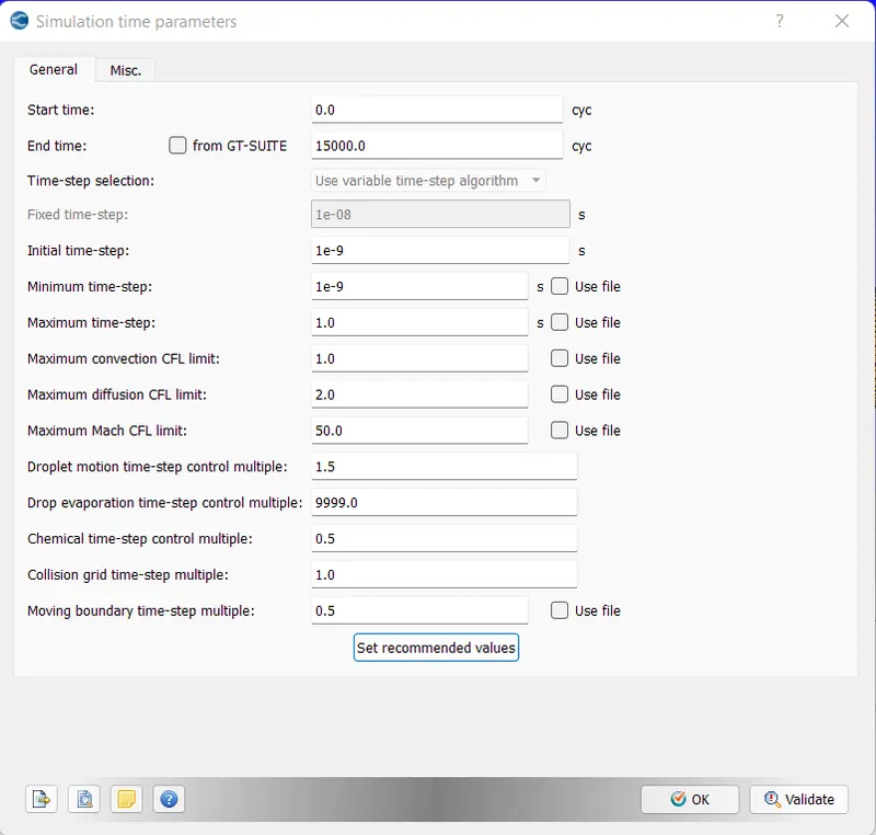
Turbulence Model = Default
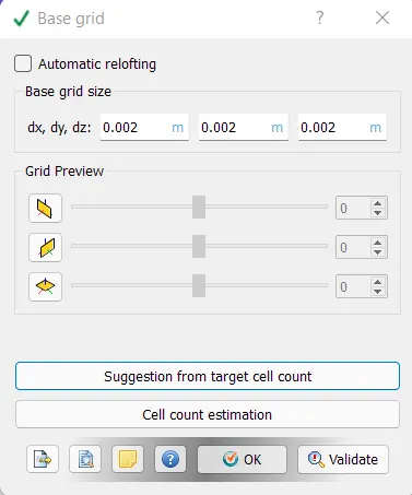
Base grid = 4e-3m
Post Processing = Default options
Output files = default options
Simulation
Following command is used:
mpiexec.exe -n 4 converge.exe restricted
Steady State Simulation
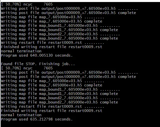
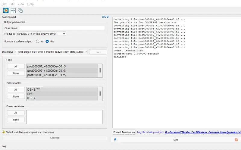
Post conversion
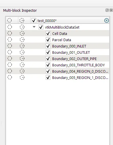
Multi-block Inspector
Purpose: To visualize defined boundary layers in Paraview
view > Multi-block Inspector
Initial Mesh
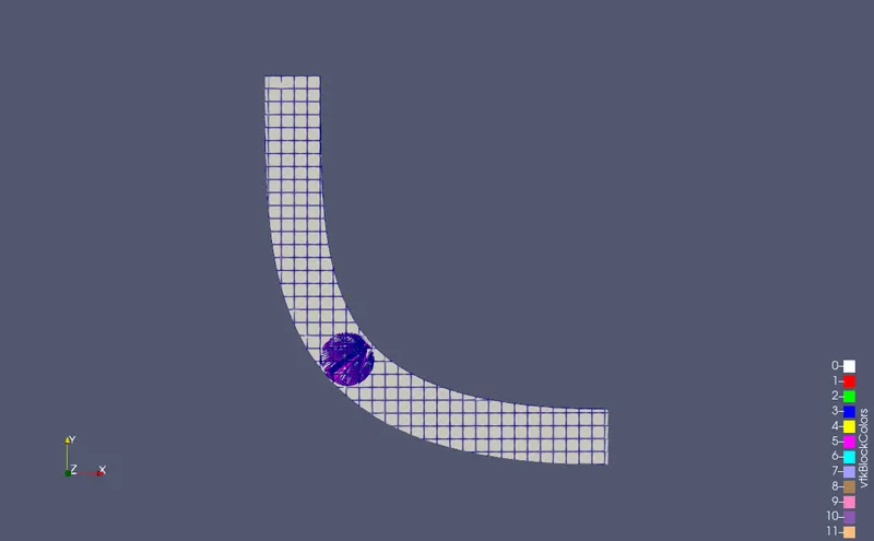
Final Mesh
Mesh after "Fixed Embedding" option activated
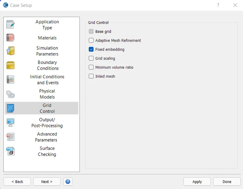
Fixed embedding
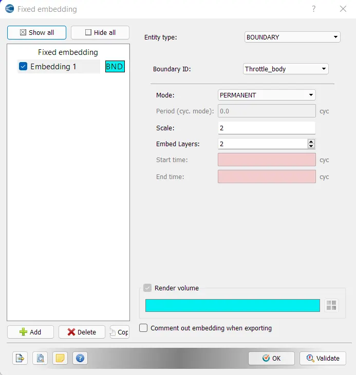
In above dialogue box, we are aplying embedding feature specifically to the throttle body.
Scale defines the element size scaling factor. In our case, 2 means the element size will be half of the global element size.
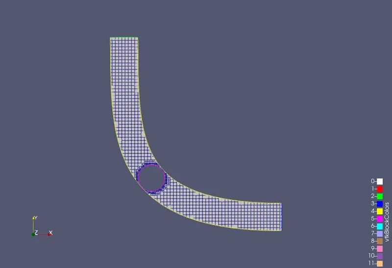
Embedded layer defines the number of element layers in surrounding of boundary. The converge will take the shape of the selected boundary to create the layers of cells.
In below imgae cell layers around throttle body can be seen.
Results
Velocity Contour
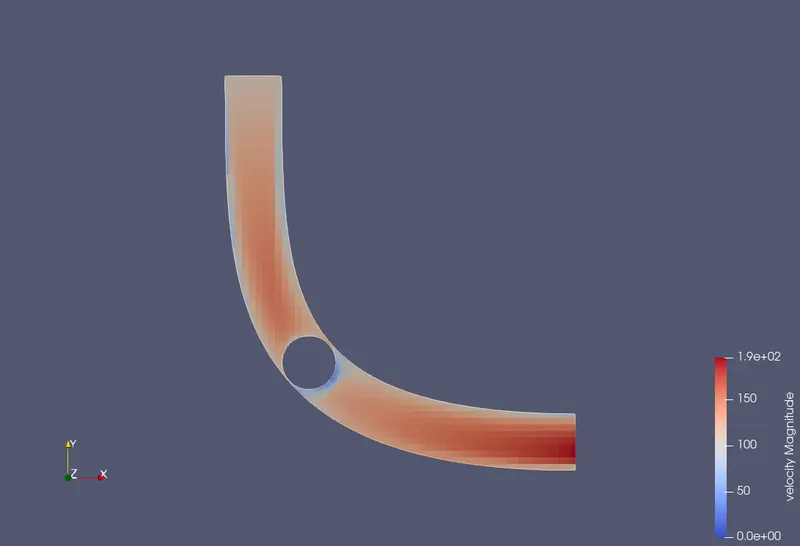
Pressure Contour
Static Pressure Plot
Mass Flow rate plot
Avg. Velocity
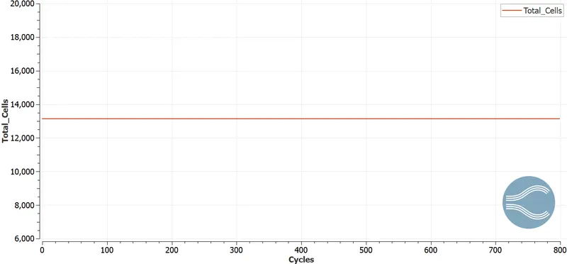
Total cell count