Week 3 Verification of Weld Joints
OBJECTIVE: The project's objective is to perform a static structural analysis on Railwheel and track and compare Total Deformation, Equivalent Stress, and life under different loading conditions. Also, implement user-defined results and compare the total deformation with the inbuilt result by ANSYS.
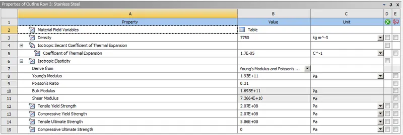
Case 1: Stainless Steel: In this case, the material of the plates must also be the same. Use Stainless steel for both weldments and plates. No need to add flux to the weldments.
Case 2: Aluminium Alloy: The material to be chosen for this case is Aluminium alloy(high strength, wrought). [Plate material to be used is stainless steel]
Case 3: Bronze: To simulate "Brazing", you should be using bronze as the weld material. Assign Stainless Steel to both plates and Copper to the "Ribs".
STEPS FOR PERFORMING ANALYSIS:
1. Open ANSYS workbench.
2. Select the static structural module.
3. Select the proper Engineering data card.
4. Import geometry.
5. Open Mechanical model.
6. Give proper connections (contacts and joints).
7. Generate mesh.
8. Set Analysis Setting as given.
9. Insert output request
10. Analyze Result.
ANALYSIS SETUP:
GEOMETRY
Import given model in ANSYS Workbench for static structural analysis.
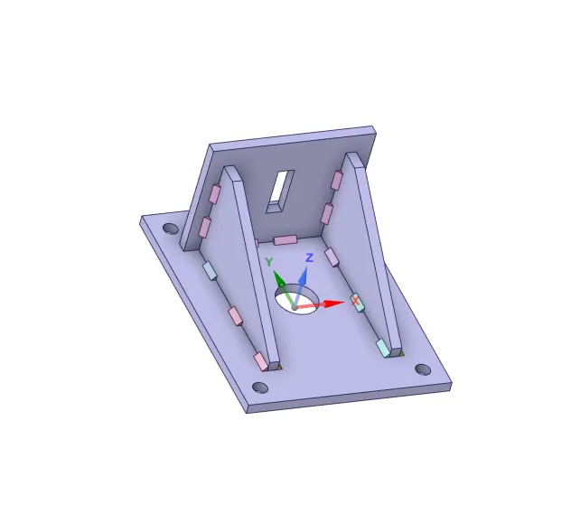
Fig. CAD Model
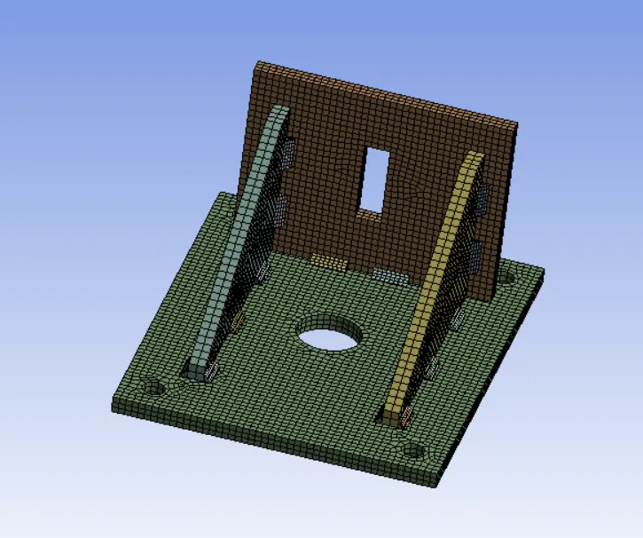
MESHED MODEL:
Details
Big plate and small Plate = 5mm
Ribs = 4mm
No of nodes = 83397
No. of elements = 15428
PROCEDURE FOR ALL CASE:
1. Import model in ANSYS Workbench.
2. Assign material properties.
3. Open the mechanical module where we going to perform analysis.
4. Meshed the model with desired element size.
5. Now after meshing, From Project Tree, select "Connections" and create "Contact".
- Contacts:
- First, select all weld in the contact tree and assign " Type = Bonded "
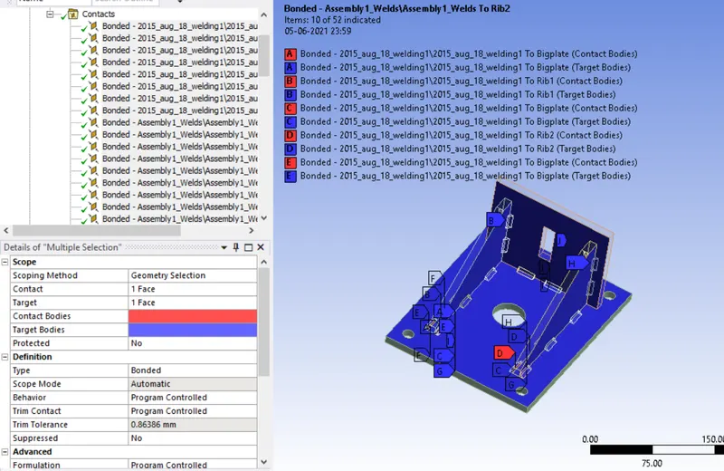
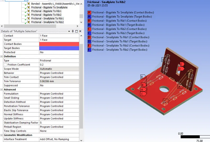
- Now for the contact between plate and ribs, ribs and plate.
Type = Frictional
Frictional Coeff = 0.2
6. BOUNDARY CONDITIONS:
Now let's define the Boundary condition.
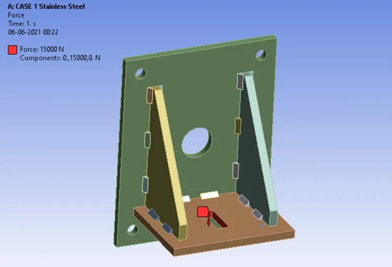
- Here we are going to look at stress developed in the component while applying a load of 15000 N.
- In the analysis setting Turn on Large deflection and leave all the settings as default.
- Other boundary conditions are given below:
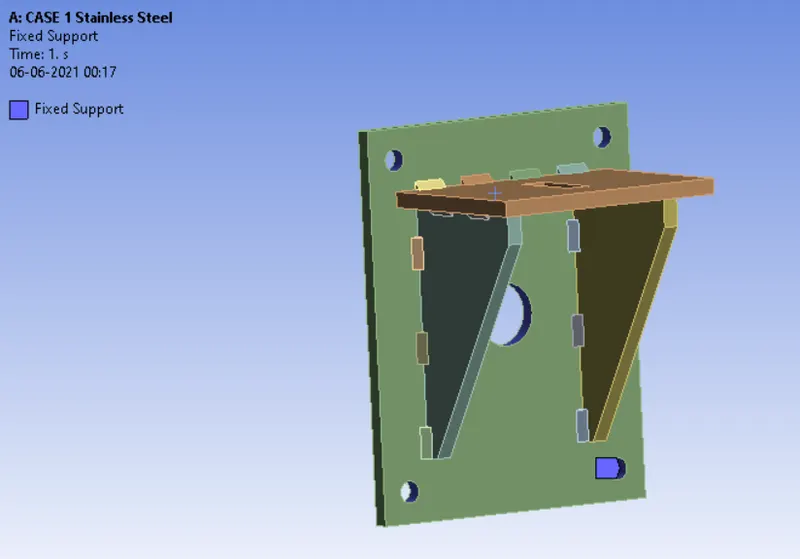
1: Fixed Support: Select all hole of the Big Plate.
2. Force: Now apply a load of 15000 N to the hole of the Small Plate.
7. SOLUTION:
- After giving proper Boundary conditions, create a solution for the output result.
1. Equivalent Stress (Von-misses), Equivalent Elastic Strain and Total Deformation for the complete model,
2. Equivalent Stress and Strain for Ribs and Weld joints
3.Directional Deformation in the Y direction.
4. Contact tool for stress and pressure between
- Plate and Ribs
RESULT:
CASE 1:
Material: Stainless steel for both Plate and Ribs.
1. Directional Deformation:
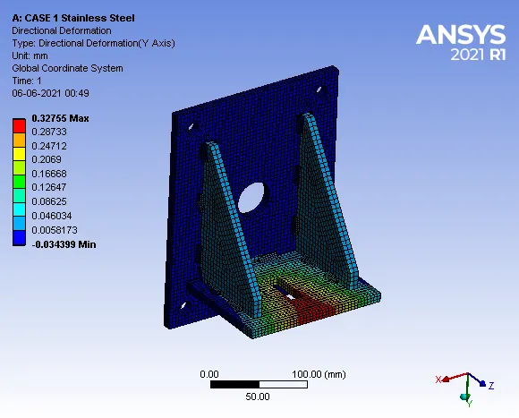
Maximum Directional Deformation = 0.32755 mm
2. Equivalent Von-Misses Stress:
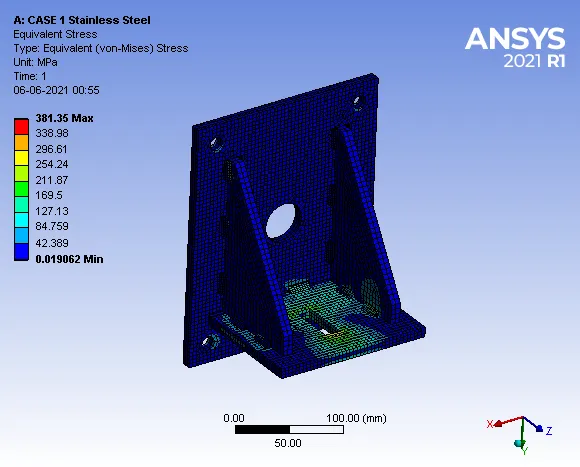
Maximum Stress = 381.35 MPa
3. Equivalent Elastic Strain:

Maximum Strain = 0.0021118 mm/mm
4. Equivalent Stress of Ribs:
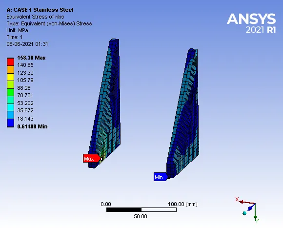
Maximum Stress = 158.38 MPa
5. Equivalent strain of Ribs:
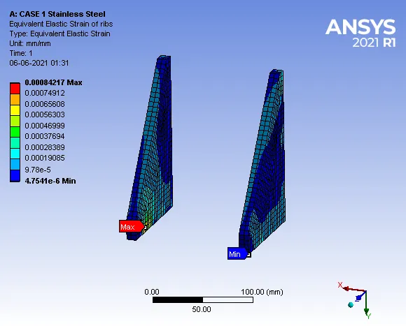
Maximum Strain = 0.00084217 mm/mm
6. Equivalent Stress of Weldments:
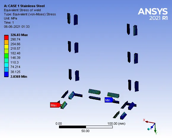
Maximum Stress = 326.83 MPa
7. Equivalent Elastic Strain of Weldments:
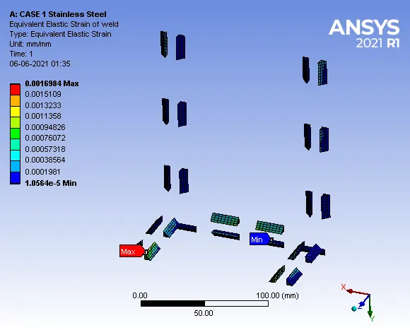
Maximum Strain = 0.0016984 mm/mm
CASE 2:
Material: Aluminium Alloy for weldments and stainless steel for the plate.
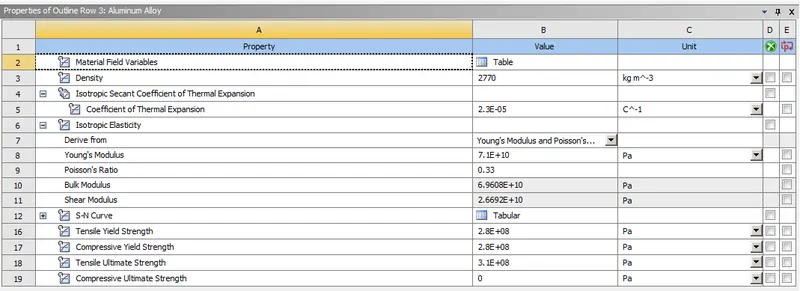
Fig. Aluminum Alloy
Fig. Stainless Steel
1. Directional Deformation in Y direction:
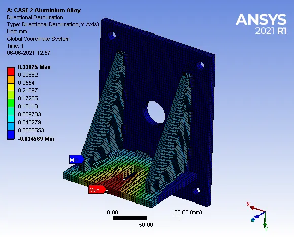
Maximum Deformation = 0.33825 mm
2. Equivalent Stress:
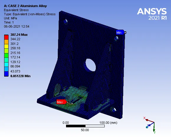
Maximum Stress = 387.24 MPa
3. Equivalent Elastic Strain:
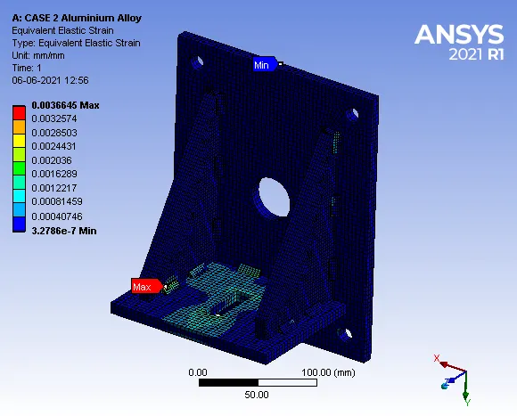
Maximum Strain = 0.0036645 mm/mm
4. Equivalent Stress of Ribs:
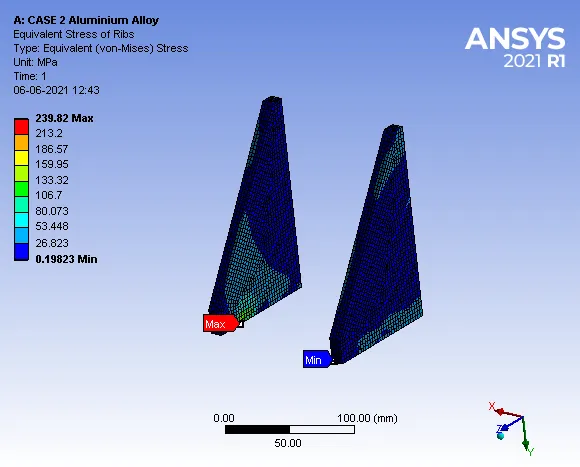
Maximum Stress = 239.82 MPa
5. Equivalent Elastic Strain of Ribs:
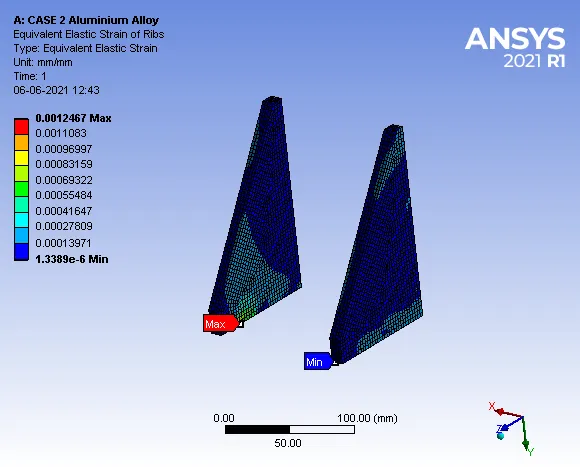
Maximum Strain = 0.0012467 mm/mm
6. Equivalent Stress of Weldments:
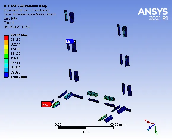
Maximum stress = 259.95 MPa
7. Equivalent Elastic Strain of Weldments:
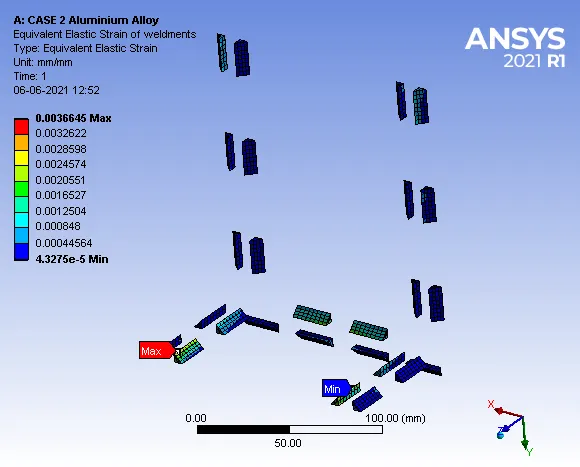
Maximum Strain = 0.0036645 mm/mm
Case 3:
Material: Bronze for weld material. Assign Stainless Steel to both plates and Copper to the "Ribs".
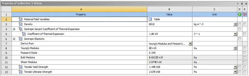
Fig. Bronze for Weldments
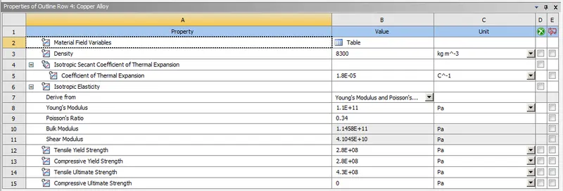
Fig. Copper alloy for ribs
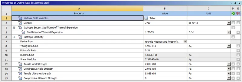
Fig. Stainless Steel for Plate
1. Directional Deformation:
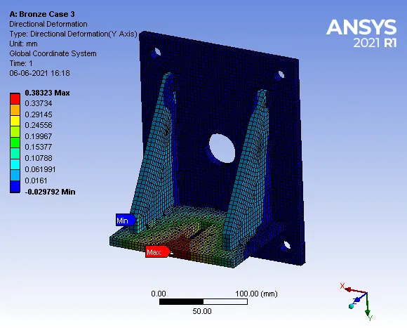
Maximum Deformation = 0.38323 mm
2. Equivalent Stress:
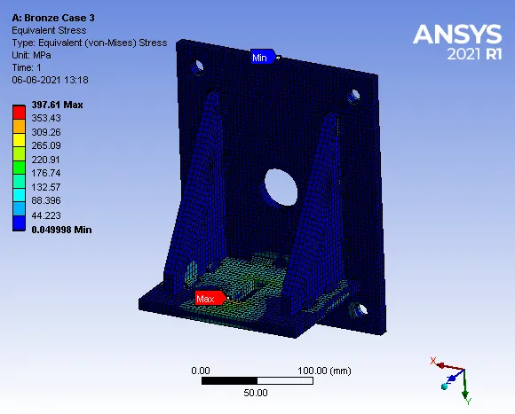
Maximum stress = 397.61 MPa
3. Equivalent Elastic Strain:
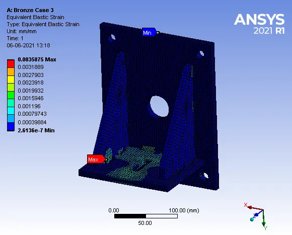
Maximum Strain = 0.0035875 mm/mm
4. Equivalent Stress of Ribs:
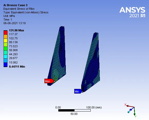
Maximum Stress = 131.98 MPa
5. Equivalent Elastic Strain of Ribs:
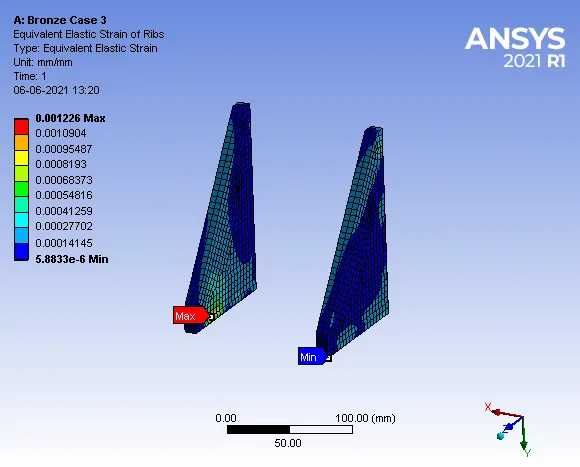
Maximum Strain = 0.001226 mm/mm
6. Equivalent Stress of Weldments:
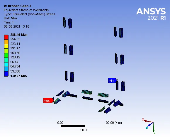
Maximum Stress = 286.49 MPa
7. Equivalent Elastic Strain of Weldments:
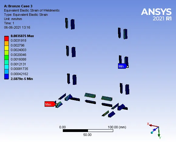
Maximum Strain = 0.0035875 mm/mm
COMPARISON:
| S No. | Directional Deformation |
Maximum Stress of Setup(MPa) |
Maximum Strain Setup(mm/mm) | Maximum Stress of Weld joint(MPa) | Maximum Strain of Weld Joint | The maximum stress in Ribs | Maximum Strain in Ribs |
| Case 1 | 0.32755 mm | 381.35 MPa | 0.0021118 | 158.38 MPa | 0.0016984 | 158.38 MPa | 0.00084217 |
| Case 2 | 0.33825 mm | 387.24 MPa | 0.0036645 | 259.95 MPa | 0.0036645 | 239.82 MPa | 0.0012467 |
| Case 3 | 0.38323 mm | 397.61 MPa | 0.0035875 | 286.49 MPa | 0.0035875 | 131.98 MPa | 0.001226 |
Conclusion: As per the above results, we can see that in case 3, stress developed in setup is 397.61MPa and stress developed in weldments is 286.49MPa and also the directional deformation is more as compared to the rest of the cases. case1 has lesser stress, strain and directional deformation.
So it can be inferred from the analysis that stainless steel as weldments experience lesser stress as compared to aluminium and bronze.