Week 3 Verification of Weld Joints
Weld Joint Analysis using ANSYS Workbench:
Aim:-
To study and perform analysis on the weld joints using different materials for the welds and compare the result with each other.
Weld material used
Case 1: Stainless Steel for all the components.
Case 2: Aluminium Alloy for weld parts and stainless steel for ribs and plates.
Case 3: Bronze for weld parts, Stainless steel for plates and copper for ribs.
Analysis Set-up for Sheet metal:-
Case 1:-
I. Geometry:-
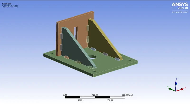
The CAD model is imported in Ansys static structural environment. It comprises of four different components named as Big plate, small plate, Ribs and Welded components. Then it is viewed in spaceclaim and it is sure that now error should be present in geometry, otherwise it will make problem while solving set-up.
II. Materials:-
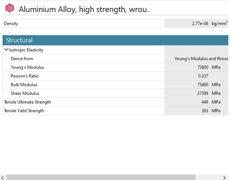
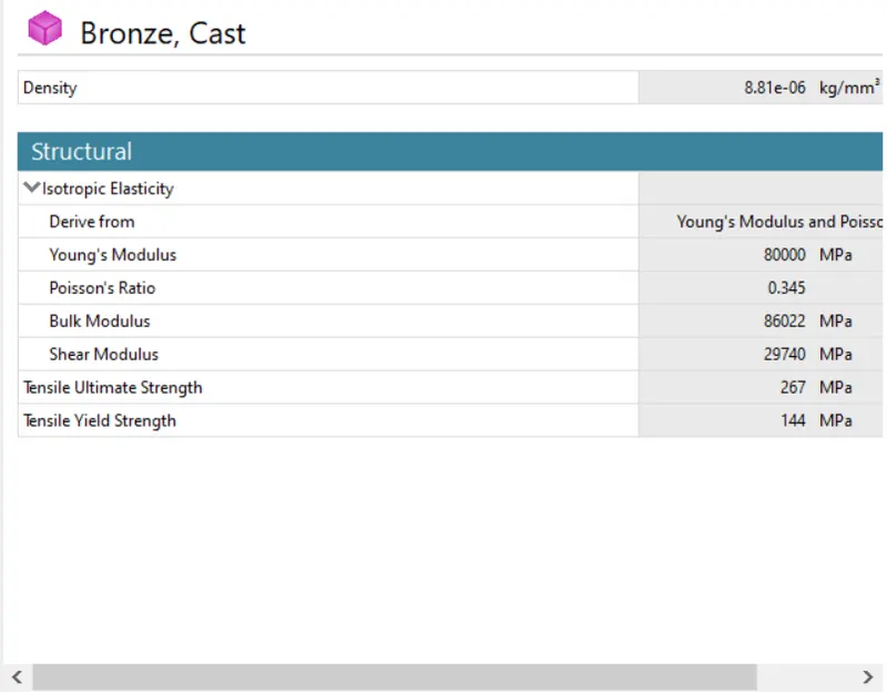
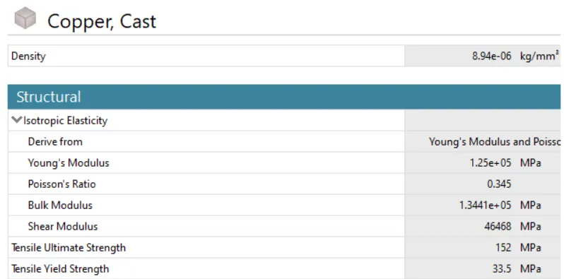
Below are the materials which is used to perform analysis for the sheet metal. The analysis is carried out for each material individually.
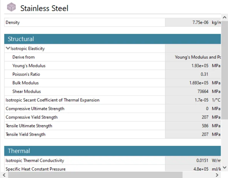
Case 1: Stainless Steel
Case 2: Aluminium Alloy for weld parts and stainless steel for ribs and plates.
Case 3: Bronze for weld parts, Stainless steel for plates and copper for ribs.
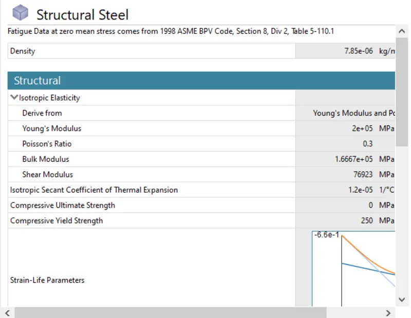
The detailed engineering data of material is as shown in image below:
III. Connection Details:-
Contact Details:
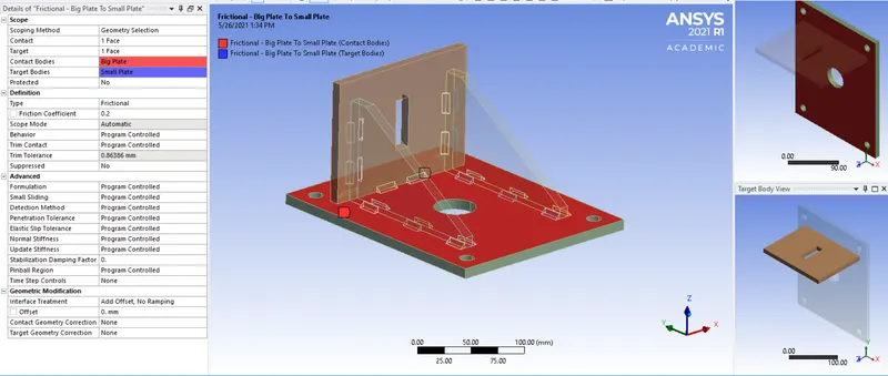
a. Frictional- From Big plate to small plate
In this type of contact, the contact has selected 1 face in which the target also has selected 1 face as big and small plate. The definition used for this type of contact is frictional with frictional coefficient of 0.2.
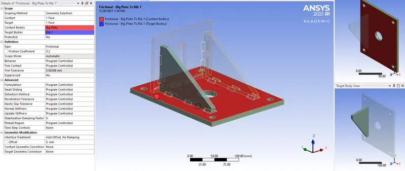
b. Frictional- From Big plate to Rib 1
In this type of contact, the contact has selected 1 face in which the target also has selected 1 face as Big plate and Rib 1. The definition used for this type of contact is frictional with frictional coefficient of 0.2.
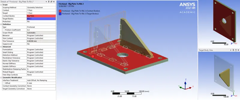
c. Frictional- From Big plate to Rib 2
In this type of contact, the contact has selected 1 face in which the target also has selected 1 face as Big plate and Rib 2. The definition used for this type of contact is frictional with frictional coefficient of 0.2.
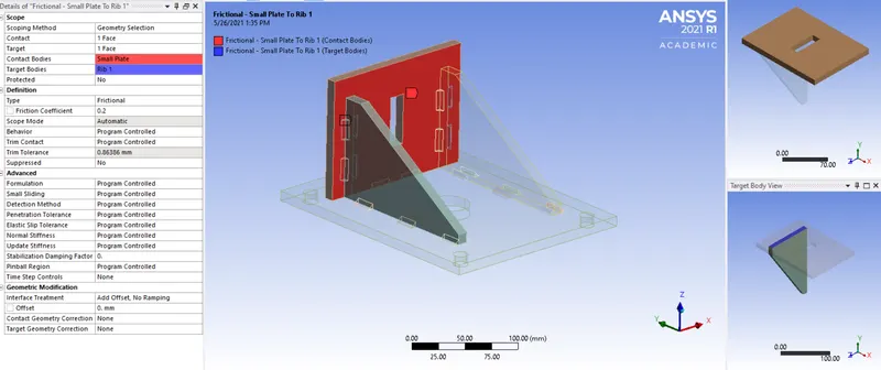
d. Frictional- From Small plate to Rib 1
In this type of contact, the contact has selected 1 face in which the target also has selected 1 face as Small plate and Rib 1. The definition used for this type of contact is frictional with frictional coefficient of 0.2.
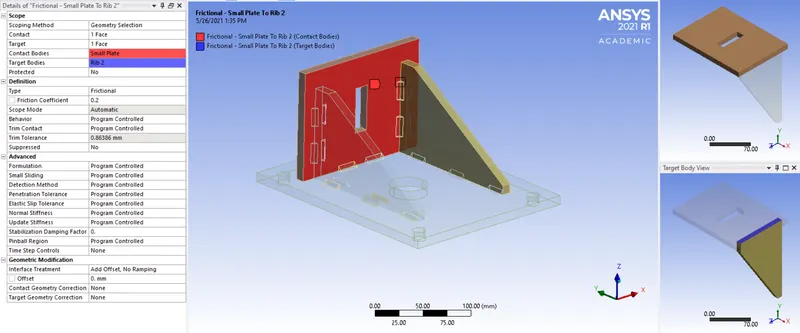
e. Frictional- From Small plate to Rib 2
In this type of contact, the contact has selected 1 face in which the target also has selected 1 face as Small plate and Rib 2. The definition used for this type of contact is frictional with frictional coefficient of 0.2.
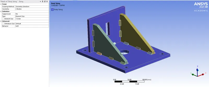
IV. Mesh:-
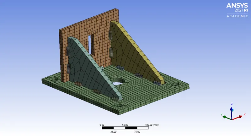
The mesh is created such that the stresses converge. Body sizing is used for each of the parts sepreately. The sizing is given for small and big plate with a mesh of 7mm mesh size, so that the mesh becomes more fine. Other portions has defaulted mesh as per its mesh size.
V. Boundary Conditions and Analysis Settings:-
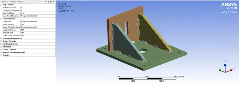
1. Analysis Settings:
The analysis setup is set for 1 steps. This does not control the time step, but it's the indication of points where boundary changes. The time step is auto controlled by specifying initial, min and max time step.
2.Boundary Conditions:
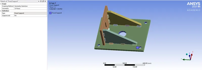
a. Fixed Support:
As, we have to give fixed support over the 5 holes for the base plate for running the solution. We have to select the faces using geometry selection option.
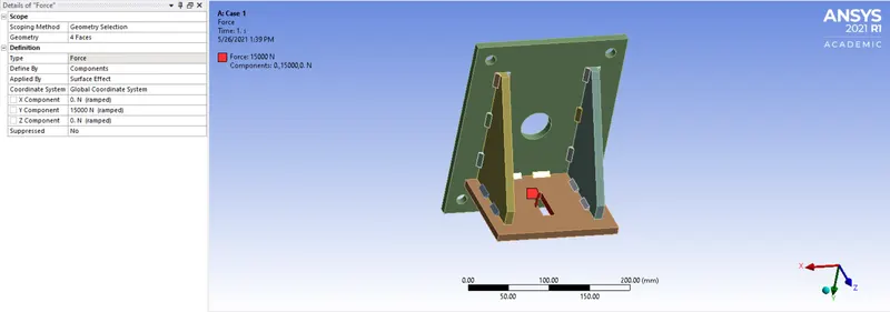
b. Force:
Then, we have to know the result that when the force is applied along the Y-axis, then what will be its deformation, stress developed across the plate. So, we have to applied force of 15000 N along Y-axis to calculate the result.
VI. Post Processing and Results:-
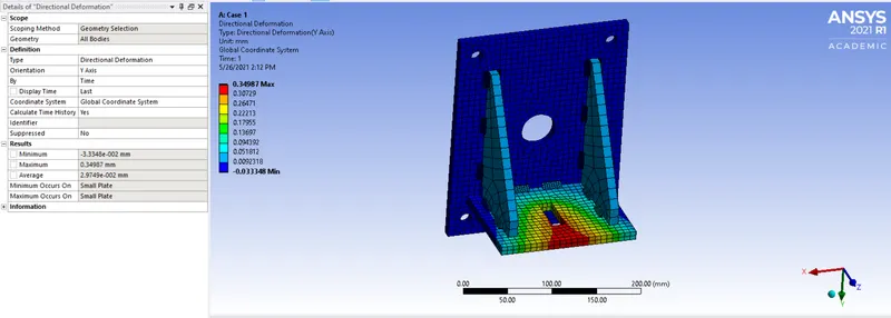
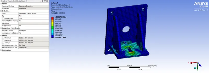
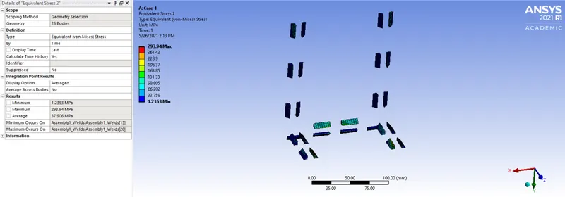
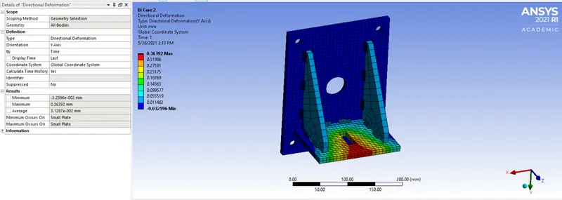
Now, we have to compare the deformation and stress on the basis of different materials as per load of 15 KN. Then, we have to analyze the result for Directional deformation, equivalent elastic strain and equivalent stress for weld joint. The results are as shown below:
Case 1: Stainless Steel for all the components.
1. Directional Deformation:
2. Equivalent Elastic Strain:
3. Equivalent Stress for weld joints:
Case 2: Aluminium Alloy for weld parts and stainless steel for ribs and plates.
1. Directional Deformation:
2. Equivalent Elastic Strain:
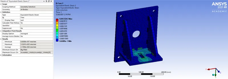
3. Equivalent Stress for weld joints:
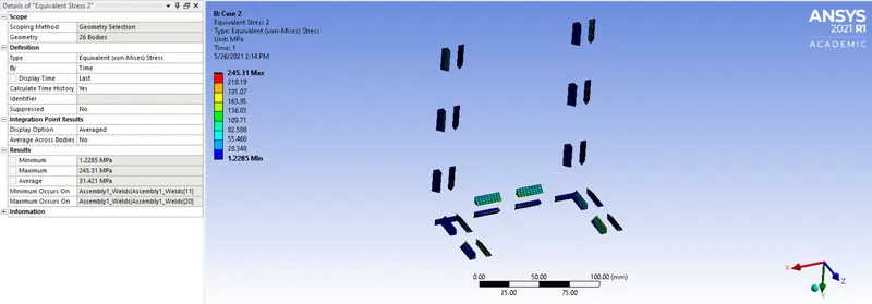
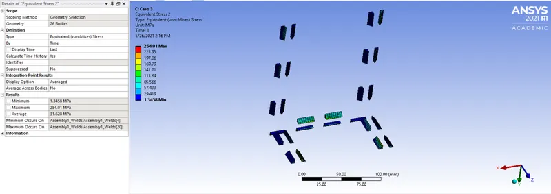
Case 3: Bronze for weld parts, Stainless steel for plates and copper for ribs.
1. Directional Deformation:
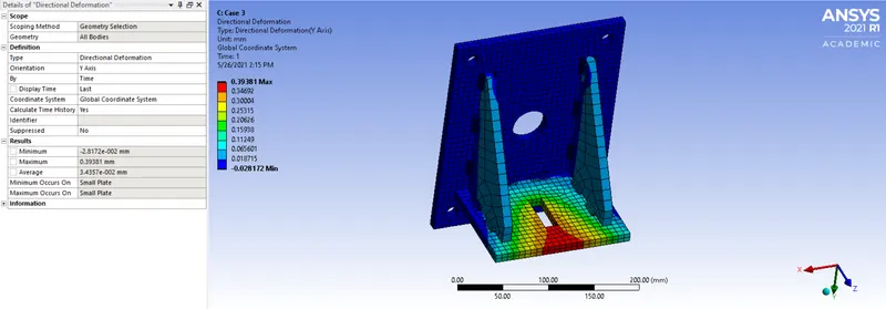
2. Equivalent Elastic Strain:
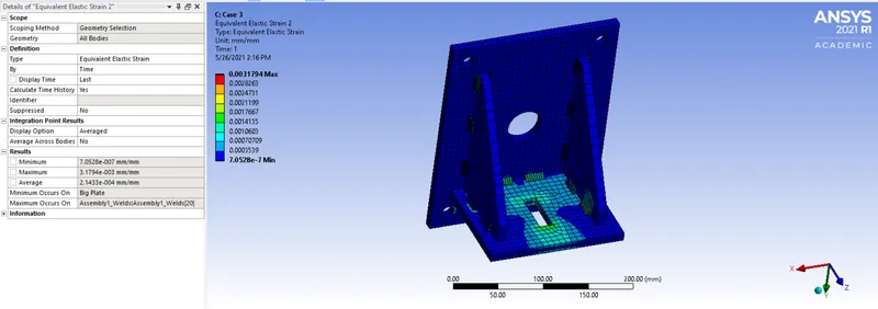
3. Equivalent Stress for weld joints:
VII. Post processing Results and Summary:-
|
Parameters |
Case 1 |
Case 2 |
Case 3 |
|
Maximum Deformation |
0.34987 mm |
0.36392 mm |
0.39381 mm |
|
Minimum Deformation |
-3.3348e-002 mm |
-3.2596e-002 mm |
-2.8172e-002 mm |
|
Maximum Equivalent elastic strain |
1.8731e-003 mm/mm |
3.3267e-003 mm/mm |
3.1794e-003 mm/mm |
|
Minimum Equivalent elastic strain |
8.3661e-007 mm/mm |
9.6089e-007 mm/mm |
7.0528e-007 mm/mm |
|
Maximum Equivalent stress for weld |
293.94 MPa |
245.31 MPa |
254.01 MPa |
|
Minimum Equivalent stress for weld |
1.2353 MPa |
1.2285 MPa |
1.3458 MPa |
Conclusions:-
- The equivalent stress of Bronze is also maximum as compared to other two materials and there is no significant difference between them as for equivalent elastic strain, it is almost same for all the materials.
- For the equivalent stress in the welds, Stainless steel has the maximum stress followed by Bronze and Aluminium alloy has the least stress.