Week 3 Verification of Weld Joints
AIM:
Simulating three different types of welding using three different weld materials, for a load of 15000N that is to be applied at the rectangular hole of the bracket. For each case, the directional deformation and equivalent strain experienced by the setup is found out to identify the weld joint that experiences the highest equivalent stress in each case and compare the results for all the three cases.
Weld Material used:
Case 1:
Stainless Steel to both weldments and plates, no flux is added to the weldments.
Case 2:
Aluminium Alloy is used for the weldments and stainless steel for the plates.
Case 3:
In order to simulate "Brazing", bronze is used as the weld material and stainless steel to the plates and copper to the ribs.
Material properties of the bronze:
Material properties of the aluminium alloy:
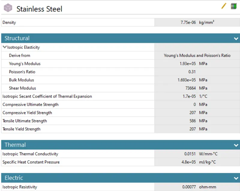
Material properties of the Stainless Steel:
Case setup and Execution:
CAD Model: There are 4 parts i.e., Big plate, small plate, ribs, and weldments.
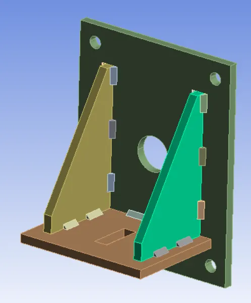
The big plate is fixed to the wall, small plate is connected to the big plate through weldments and ribs.
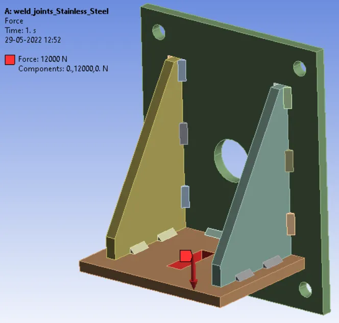
The load is naturally acted on rectangular hole of the small plate.
Contacts:
The big plate and small plate are connected using the weldments. The frictional contact is defined between the plates and ribs and the bonded contact is used for the weldments.
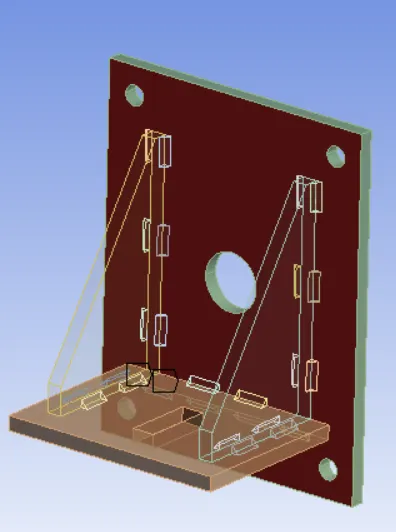
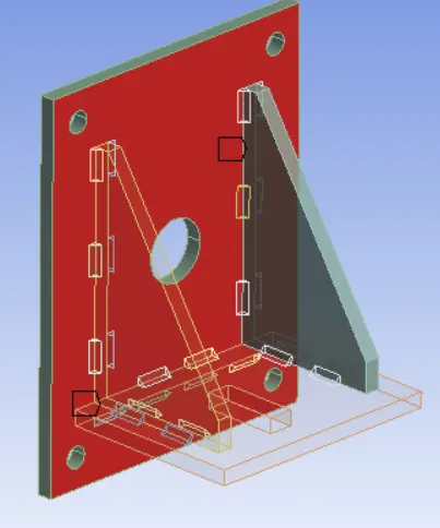
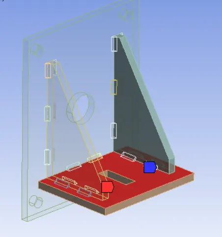
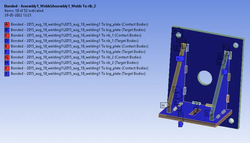
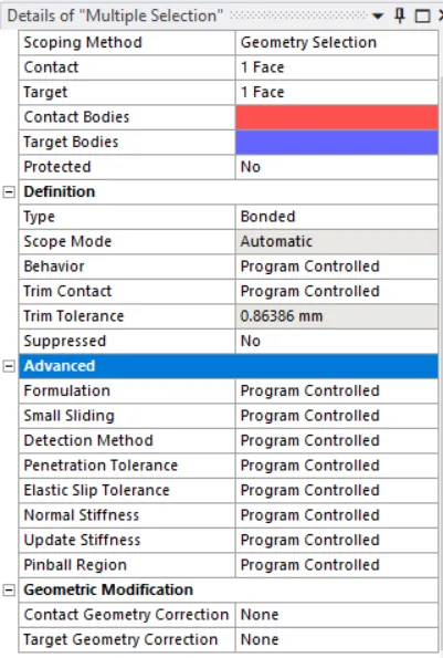
The paramters defined for the contacts are shown below:
For the weldments, the type of contact used is 'bonded'. For each weldment there are two bonded connections. For example, take a weldment between the small plate and the big plate. The bonded contact is defined between the weldment and big plate, small part and the same weldment.
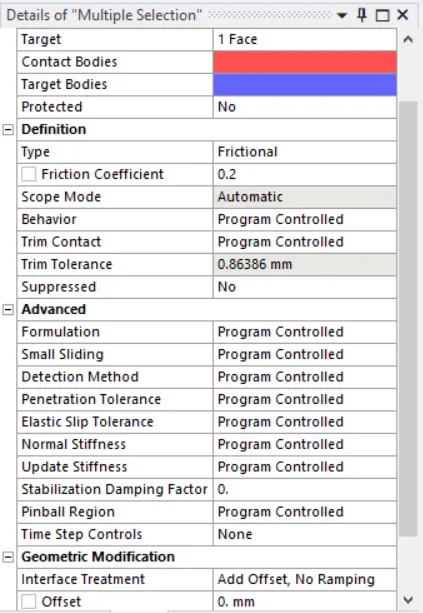
The frictional contact is defined between the plates:
the parameters ues are shown below:
Mesh:
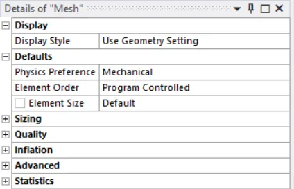
The sizing is used to generate a finer mesh on the big and small plate.
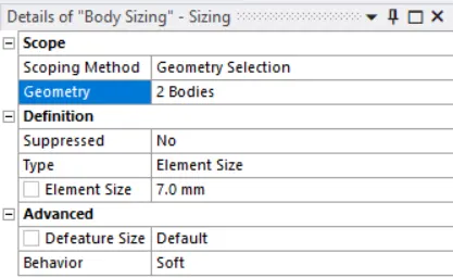
The default mesh is used on the other parts.
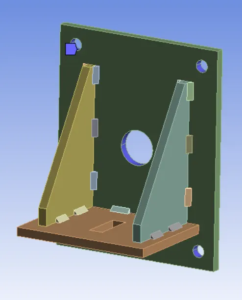
Constraints and loads applied:
The holes on the big plate are fixed in all directions.
The load is applied on the rectangular hole of the small plate.
The analysis settings used:
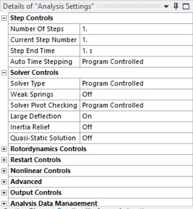
Only one step is used as the problem is very simple.
Large deflection is enabled to capture the non-linear effects.
After solving, the results are obtained by requesting the necessary outputs.
Results:
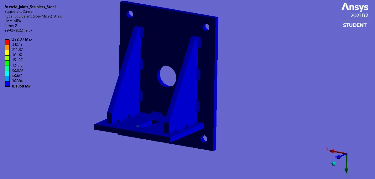
The matrial used is Stainless steel:
Von-Mises Stress:
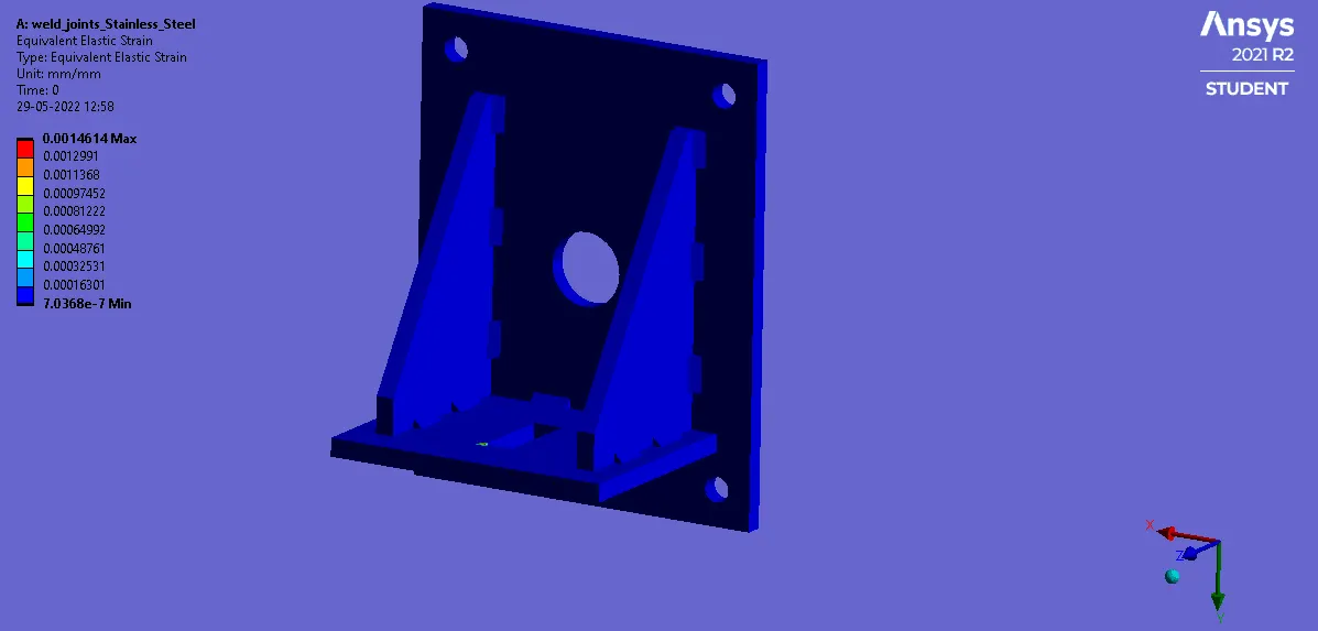
Total Strain:
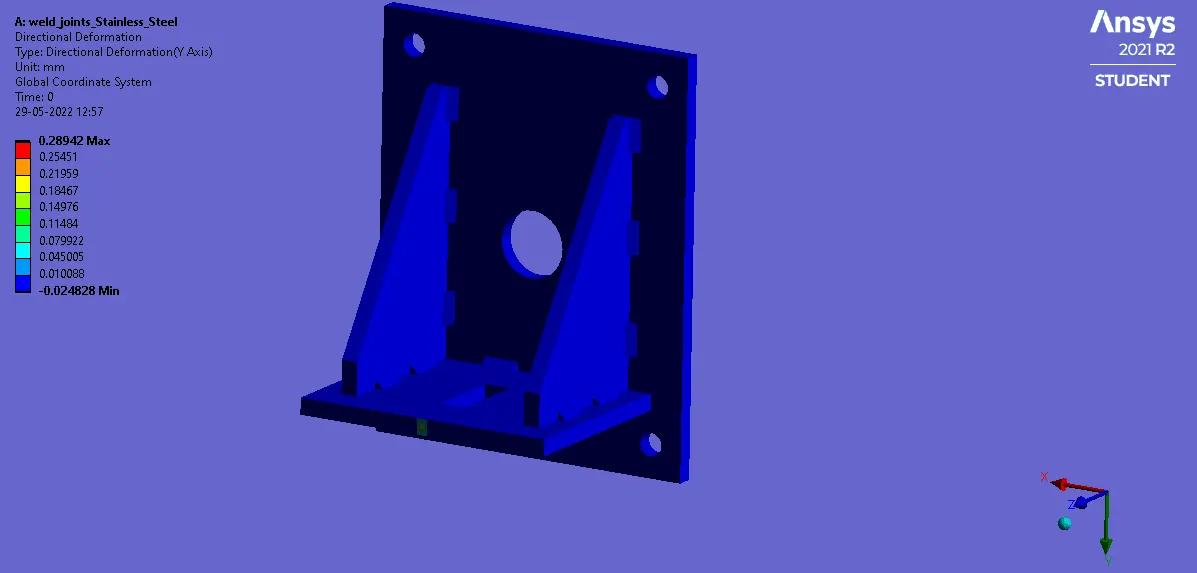
Directional deformation:
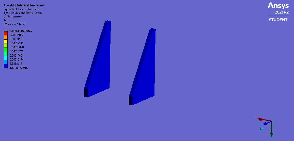
Equivalent Strain on the ribs:
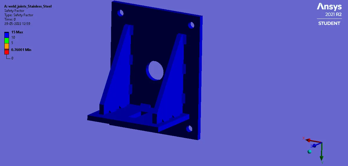
Safety factor:
Aluminium alloy:
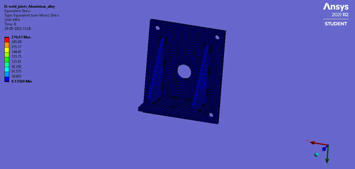
Equivalent Stress:
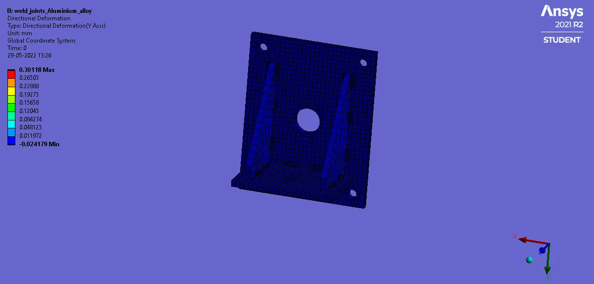
Directional deformation:
Equivalent strain:
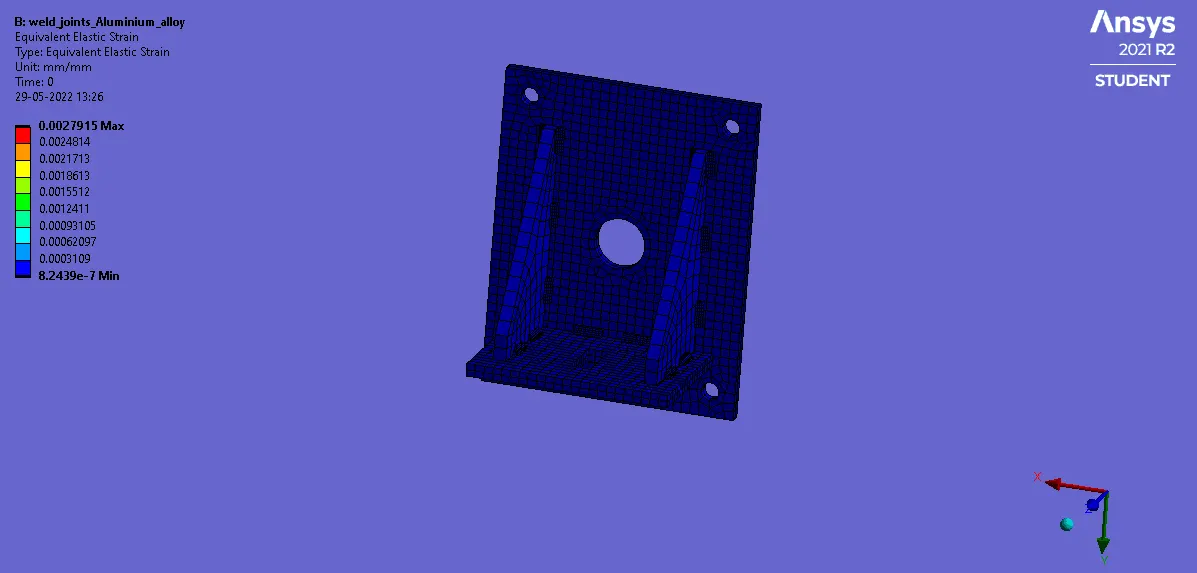
Safety factor:
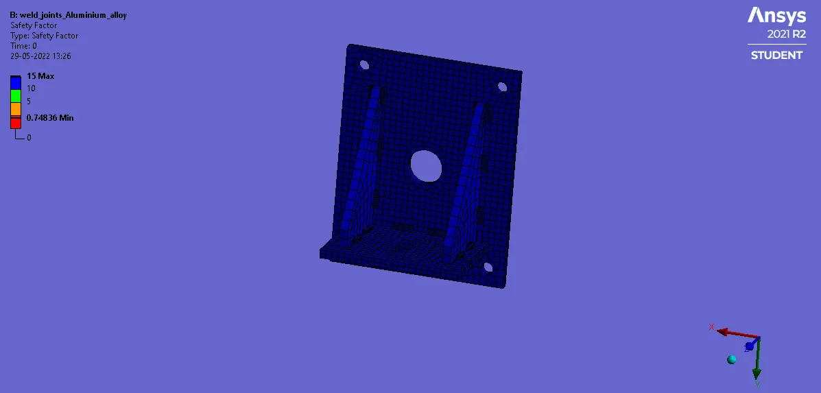
Equivalent strain on the ribs:
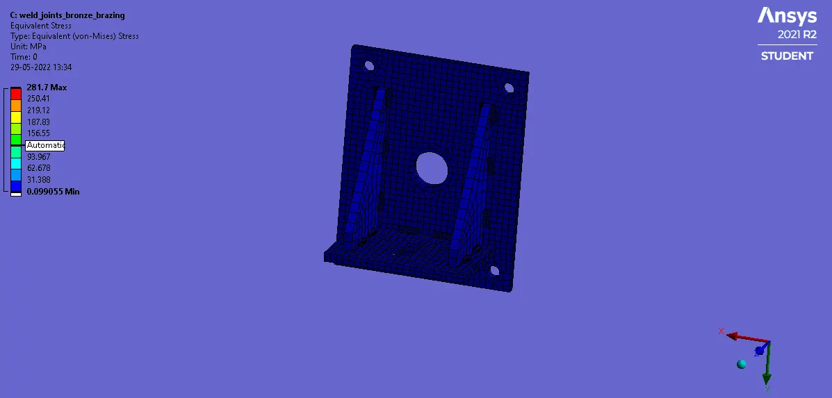
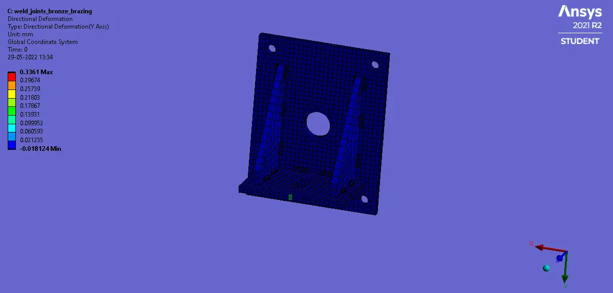
Bronze as a material for weldments:
Equivalent Stress:
Directional deformation:
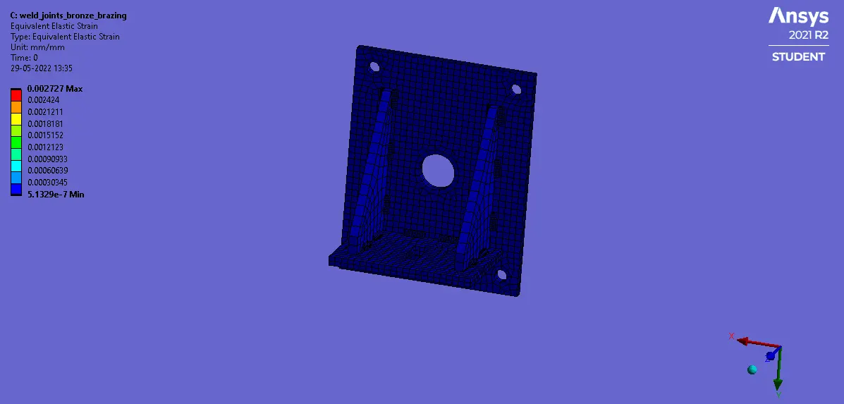
Equivalent elastic strain:
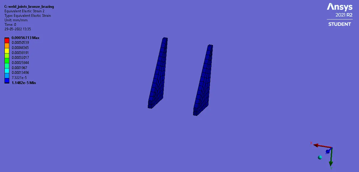
Equivalent elastic strain on ribs:
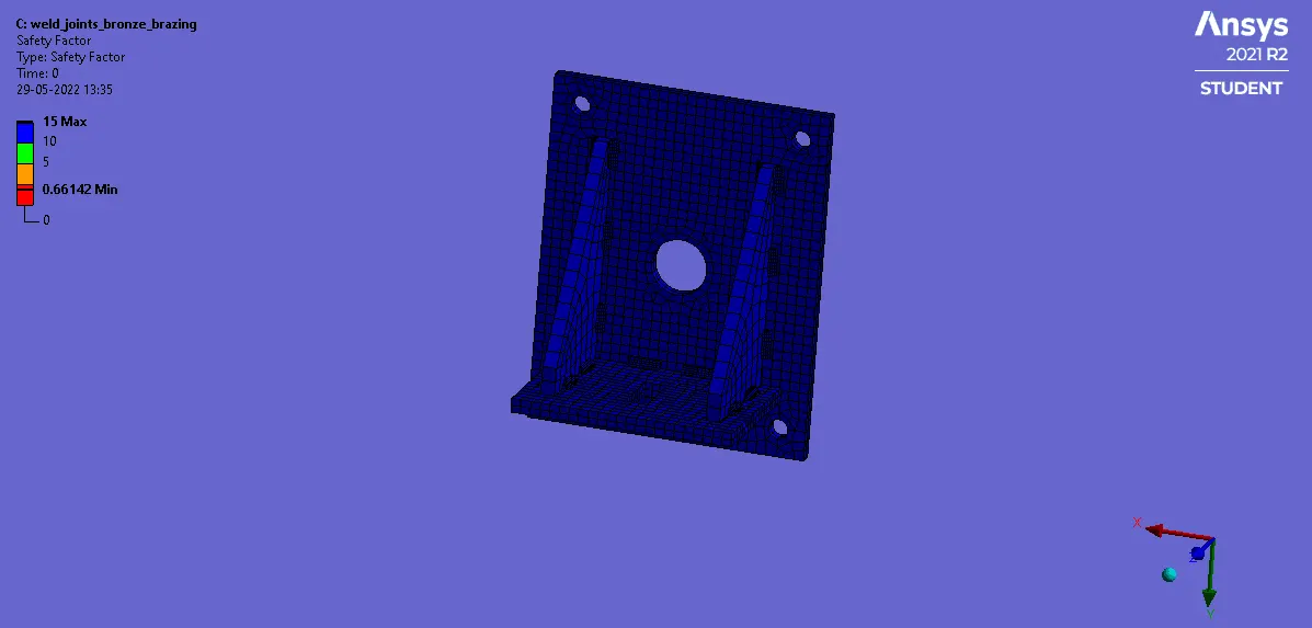
Safety factor:
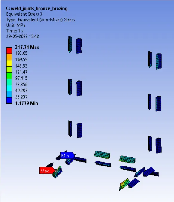
Equivalent stress on weldments:
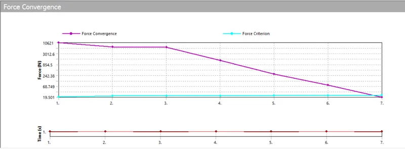
Force Convergence plot:
Usually the force is looked at as convergence criteria, in the sense that when the residual force is smaller then a force value used as criterion, then the substep is sad to be converged.
We can see that, to solve the problem it only took 7 iterations.
Comparison:

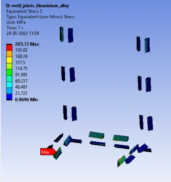
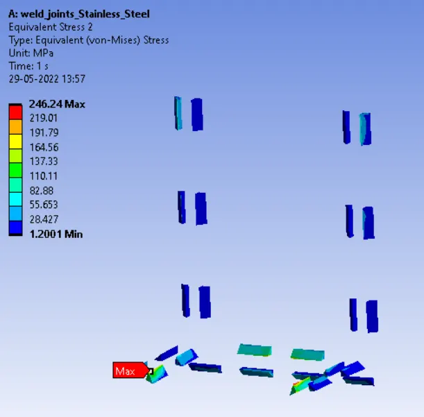
The location of maximum stress on weldments:
Bronze as weld material:
Aluminium alloy as weld material:
Stainless Steel as weld material:
Conclusion:
The motto is to learn how to verify weld joints. From the above analysis we can see there is no need of more weldments as safety factor is really good.
The maximum stress prone weldments are demonstrated.
From the results, we can say that the weldments of Stainless steel is showing less deformation, stress, strain, and good safety factor followed by Aluminium alloy and Bronze.
By analysing the weld joints, we can modify the number of weldments, we will get to know which weldment is prone to maximum stress, and the way the deformation is happening on the ribs either inwards or outwards.