Week 3 Sheet metal Bending challenge
Objective: Carrying out a finite element analysis for bending a sheet using Punch and Die and calculating Stress, Strain and Deformation produced on a sheet of different material and in different simulation parameters.
Case 1:Aluminium Alloy 1199, Copper Alloy NL and Magnesium Alloy NL. Find out the Equivalent stress, Equivalent elastic strain and Total Deformation in the Y direction and compare the results for the three materials.
Case 2:With the material as Aluminium Alloy, change the friction coefficient to 0.19 and run the analysis as in Case 1. Compare the results with that in case 1.
Case 3: Refine the mesh on the plate, With Aluminium alloy as material, run the analysis as in Case 1 and compare the results.
Modelling:
In a sheet bending process, the sheet is placed on a die, which has a valley like opening. A punch applies a force on the sheet and plastically deforms it at the point of contact till the sheet starts touching the die opening sides. The main motive of the process is the plastic deformation of the sheet and according to the material of the sheet, the appropriate force needs to be applied to the sheet by the punch to plastically deform it, i.e the stresses generated in the sheet due to the punch should be beyond the yield strength of the sheet material.
In the model, the die is kept fixed at a place and the punch has a downward motion. Here a downward displacement to the punch is a more suitable boundary condition than a load because the displacement specification means that the punch has to travel the specified distance and thus the sheet will deform that much. The force applied to the sheets gets adjusted based on the amount of deformation the sheets have to go through for the specified punch movement, meaning that the sheet's stresses will be enough for the plastic deformation irrespective of the sheet material.
STEPS FOR PERFORMING ANALYSIS:
1. Open ANSYS workbench.
2. Select the static structural module.
3. Select the proper Engineering data card.
4. Import geometry.
5. Open Mechanical model.
6. Give proper connections (contacts and joints).
7. Generate mesh.
8. Set Analysis Setting as given.
9. Insert output request
10. Analyze Result.
ANALYSIS SETUP:
GEOMETRY
Import given model in ANSYS Workbench for static structural analysis.
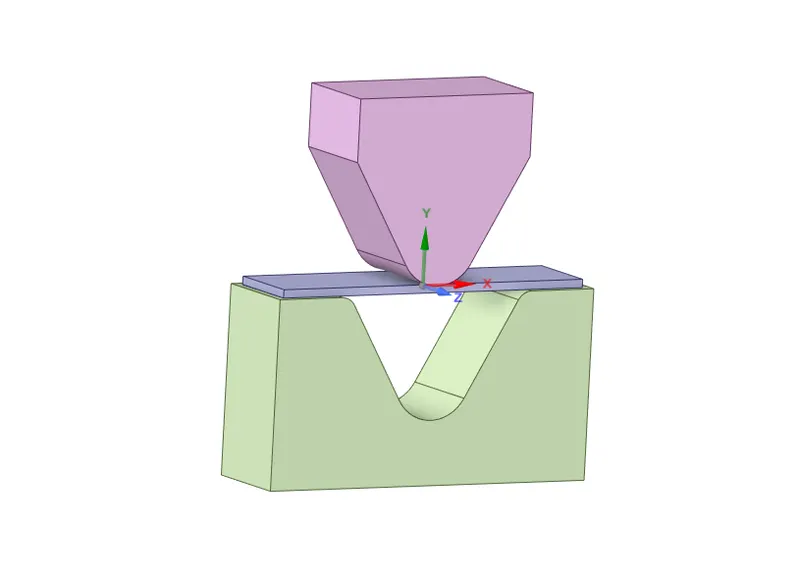
Fig. CAD Model
MESHED MODEL:
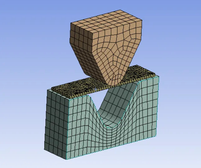
Fig. Meshed Model
Details
1. Punch and Die = 3mm
2. Sheet = 1mm
- Method = Tetrahedrons
3. Face Sizing = 2mm
No of nodes = 14561
No. of elements = 5514
PROCEDURE FOR ALL CASES:
1. Import model in ANSYS Workbench.
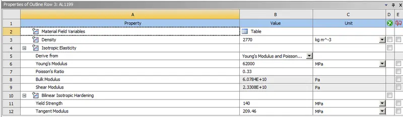
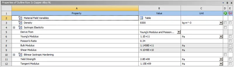
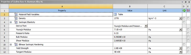
2. Assign material properties.
3. Open the mechanical module, where we going to perform analysis.
4. Meshed the model with desired element size.
5. Now after meshing, From Project Tree, select "Connections" and create "Contact".
- Contacts:
- Contact Type = Frictional
- Frictional Coeff. = 0.1
- Behaviour = Asymmetric
- formulation = Augmented Lagrange
- Normal Stiffness Factor = 0.1
- Interface treatment = Add Offset, Ramped Effects.
- The first contact between Punch and Sheet, where Punch applies a load on the sheet, So punch is contact body and sheet is target body.
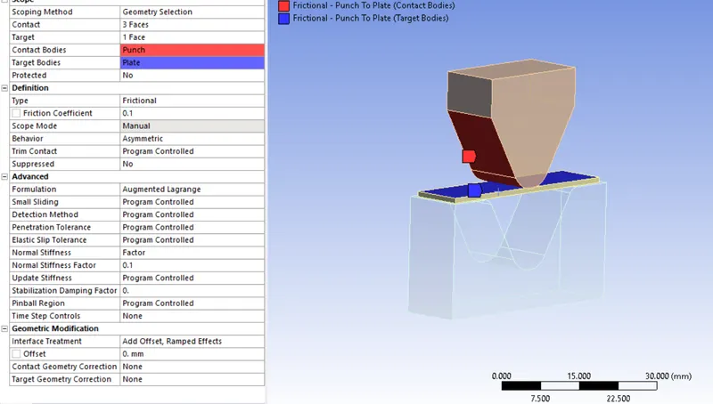
Fig. Contact between punch and sheet.
- Second contact between Sheet and Die, where load transfer from sheet to die, So Sheet is contact body and Die is target body.
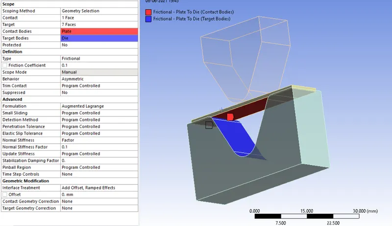
Fig. Contact between Die and Sheet
6. BOUNDARY CONDITIONS:
Now let's define the Boundary condition.
- Here we are going to look at stress, Strain and Deformation developed in the Sheet during punching operation.
- In the analysis setting
- A number of Steps = 10.
- Solver type = Direct.
- Turn ON Large deflection.
- In Non-Linear controls:-
- Stabilization = Constant
- Method = Energy
- Energy Disipitation Ratio = 0.1
- Other boundary conditions are given below:
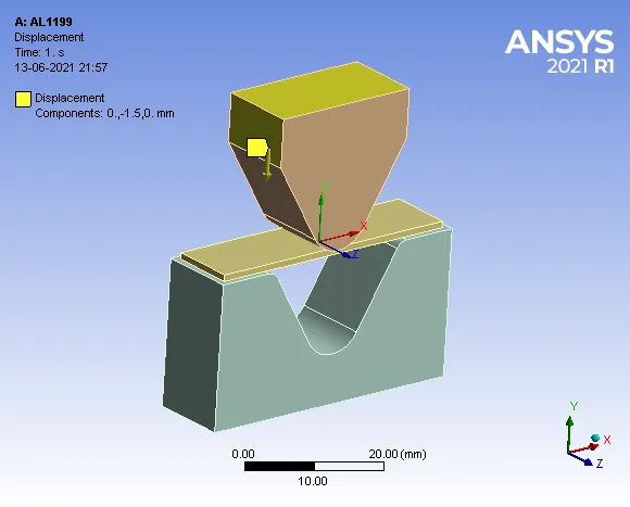
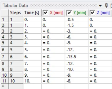
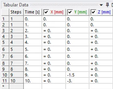
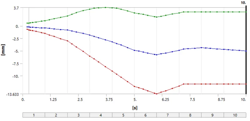
1. Displacement of Punch In Y-Direction.
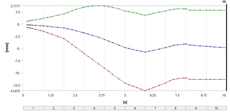
- Here Punch moves in downward in Y direction up to -13.5mm as shown in Table and reverts.
2. Displacement of Sheet.
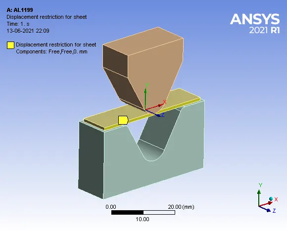
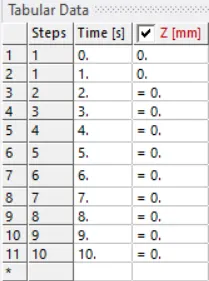
- To restrict the motion of the Sheet in the Z direction.
- Now define by components.
- X and Y components should be free and For Z define by tabular data and Put value zero for all steps as shown in Tabular data.
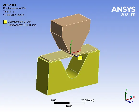
3. Displacement of Die in Y-Direction:
- After punching the sheet completely, Die should move a little bit in downward Y-direction of 3mm as shown in tabular data.
7. SOLUTION:
- After giving proper Boundary conditions, create a solution for the output result.
- Total deformation and Directional deformation in Y-Direction.
- Equivalent stress and strain of the whole model.
- Equivalent Stress and Equivalent Elastic Strain of sheet.
RESULT:
CASE 1 (A):
Material: AL1199
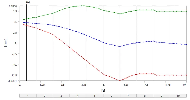
1. Total Deformation in Y-Direction :
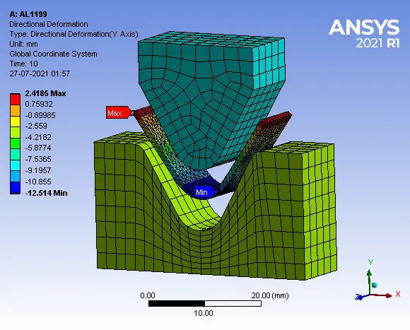
Maximum Deformation = 2.4185 mm
- Deformation Contour:
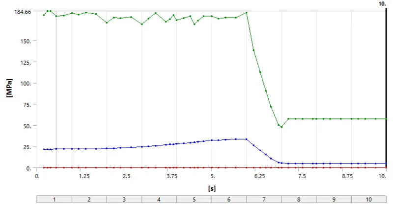
2. Equivalent von-misses Stress:
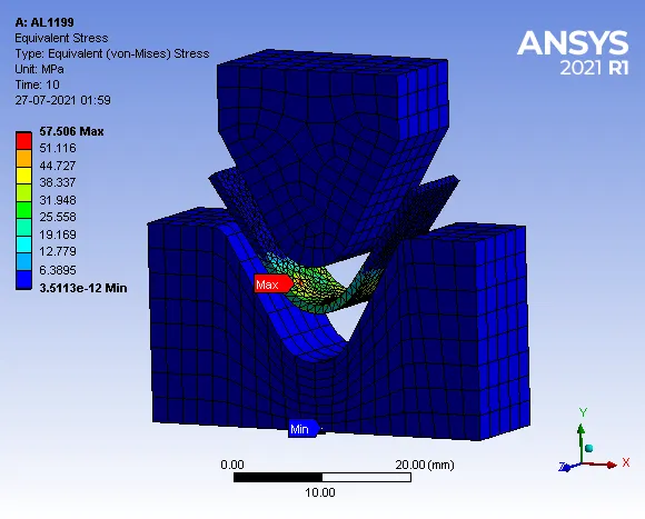
Maximum Stress = 57.506 MPa
- Stress Contours:
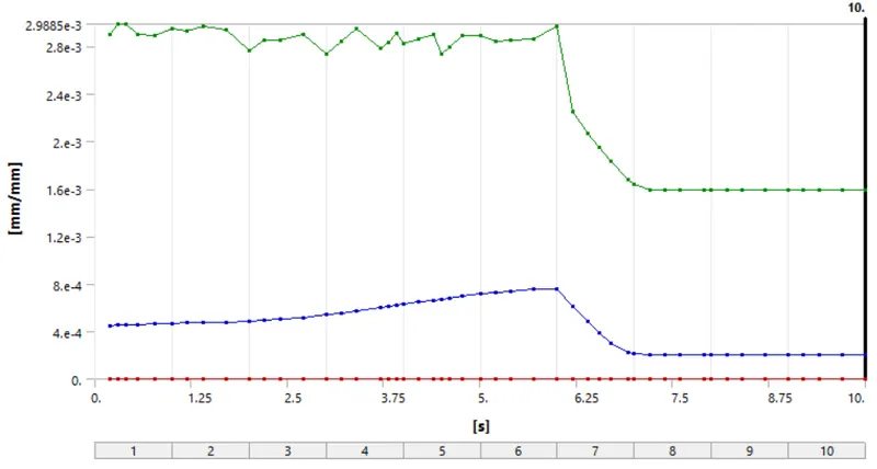
3. Equivalent Elastic Strain:
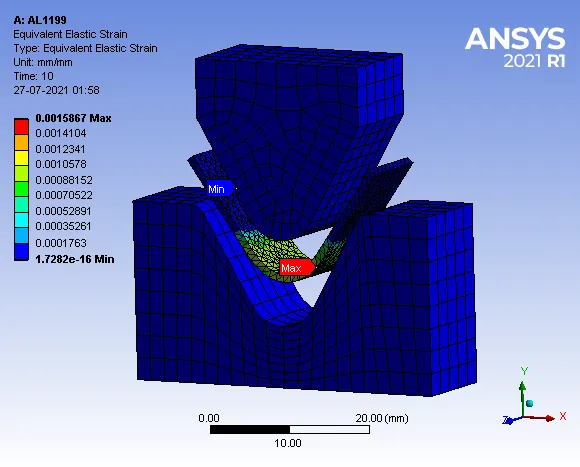
Maximum Strain = 0.0015867 mm/mm
- Strain Contours:
4. Equivalent Stress of Sheet:
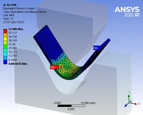
Maximum Stress = 57.506 MPa
- Stress Contours:
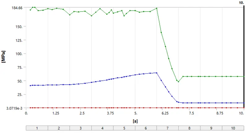
5. Equivalent Elastic Strain:
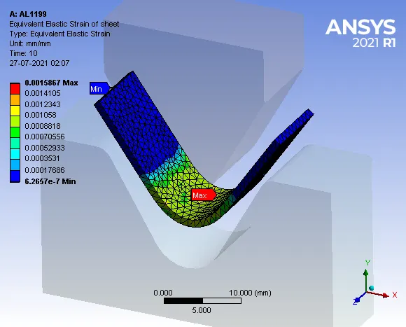
Maximum Strain = 0.001585 mm/mm
- Strain Contour
CASE 1(B)
MATERIAL: Copper Alloy NL
1. Total Deformation in Y-Direction:
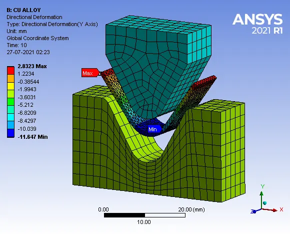
Maximum Deformation = 2.8323 mm
- Deformation Countour:
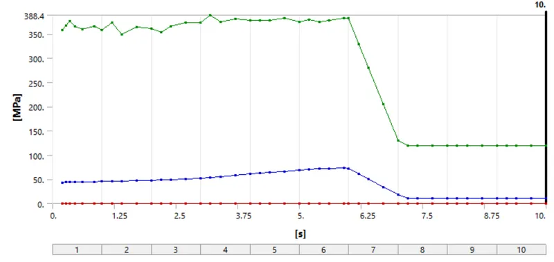
2. Equivalent von-misses Stress:
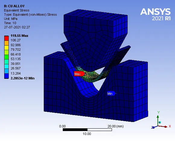
Maximum Stress = 119.57 MPa
- Stress Contour:
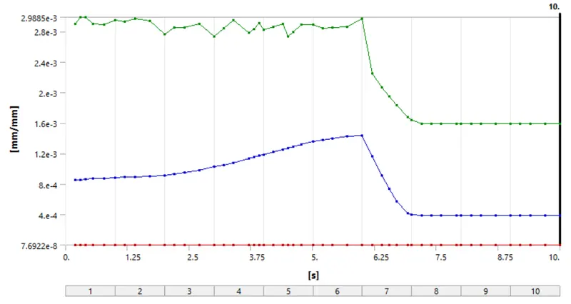
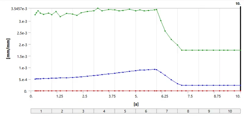
3. Equivalent Elastic Strain:
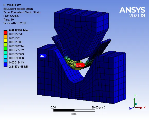
Maximum Strain = 0.0017498 mm/mm
- Strain Contour:
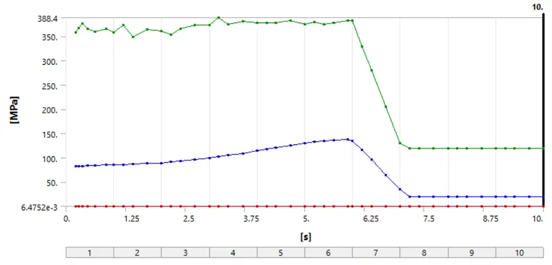
4. Equivalent stress of Sheet:
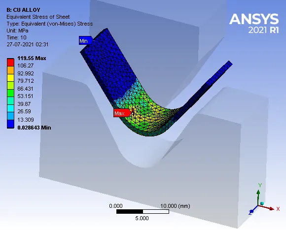
Maximum Stress = 119.55 MPa
- Stress Contours:
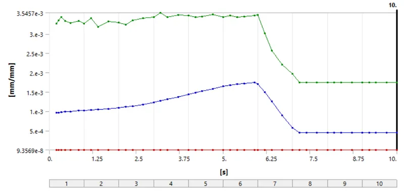
5. Equivalent Elastic Strain of Sheet:
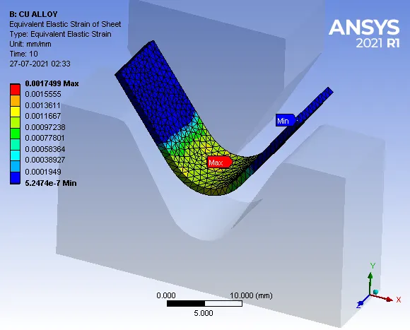
Maximum Strain = 0.0017499 mm/mm
- Strain Contours:
CASE 1(C):
MATERIAL: Magnesium Alloy NL
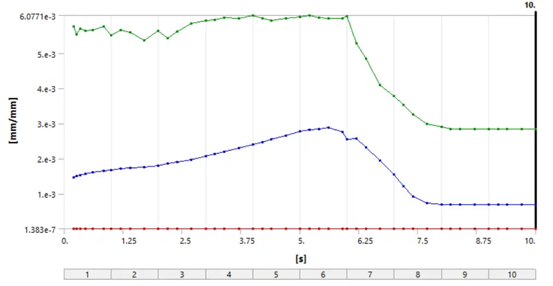
1. Directional Deformation:
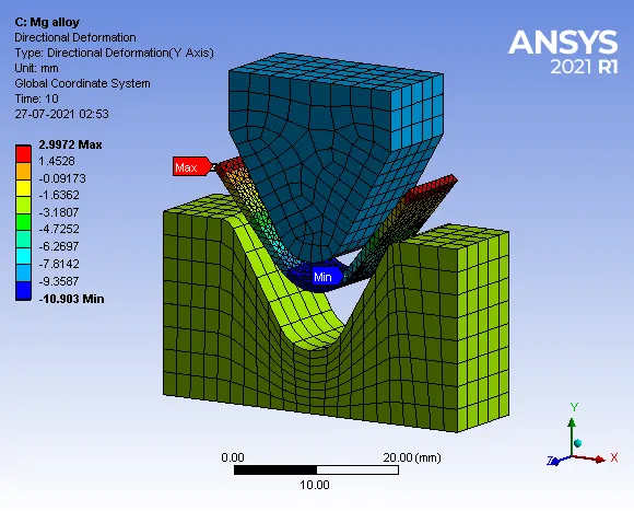
Maximum Directional Deformation = 2.9972 mm
- Directional Deformation Contours:
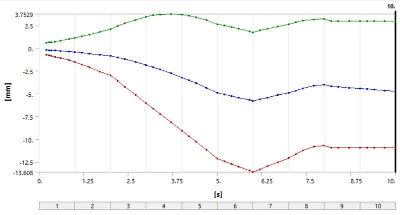
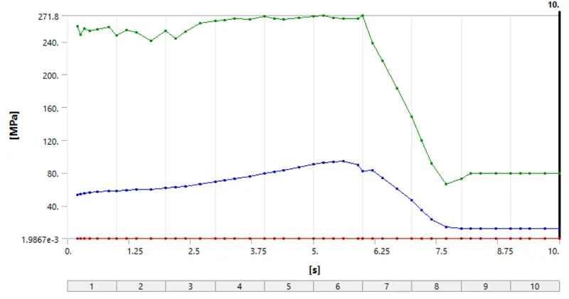
2. Equivalent von-misses Stress:
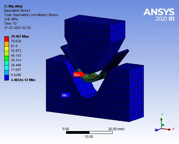
Maximum Stress = 79.457 MPa
- Stress Contours:

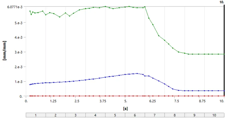
3. Equivalent Elastic Strain:
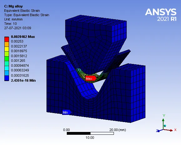
Maximum Strain = 0.0028462 mm/mm
- Strain Contours:
4. Equivalent Stress of Sheet:
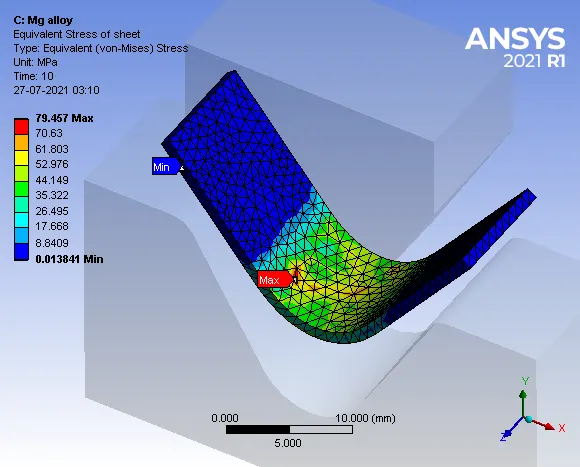
Maximum Stress = 79.457 MPa
- Stress Contours:
5. Equivalent Strain of Sheet:
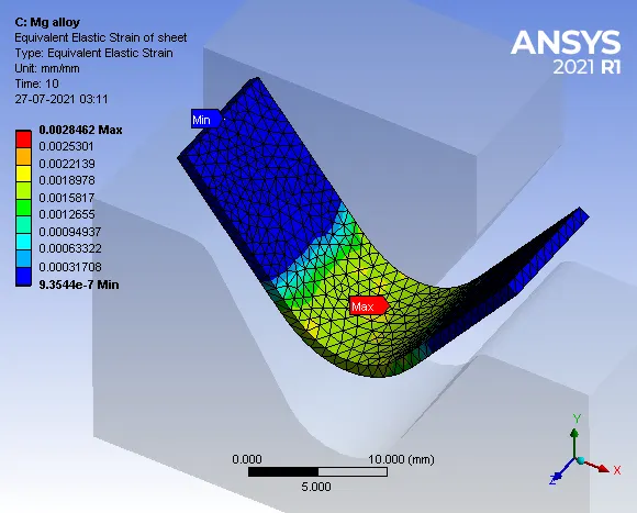
Maximum Strain = 0.0028462 mm/mm
- Strain Contours:
RESULT COMPARISON:
| S No. | Total Deformation in the Y direction | Maximum Stress of Sheet (MPa) | Maximum Strain of Sheet (mm/mm) |
|
CASE 1(A) AL 1199 |
2.4185 mm | 57.506 MPa | 0.001585 mm/mm |
|
CASE 1(B) Cu Alloy |
2.8323 mm | 119.55 MPa | 0.0017499 mm/mm |
|
CASE 1(C) Mg Alloy |
2.9972 mm | 79.457 MPa | 0.0028462 mm/mm |
CASE 2: Aluminium Alloy NL with a coefficient of friction = 0.19 and run the simulation as Case 1.
MATERIAL: Aluminium Alloy NL.
1. Total Deformation in Y-Direction:
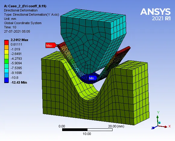
Maximum Deformation = 2.2412 mm
- Deformation Contours:
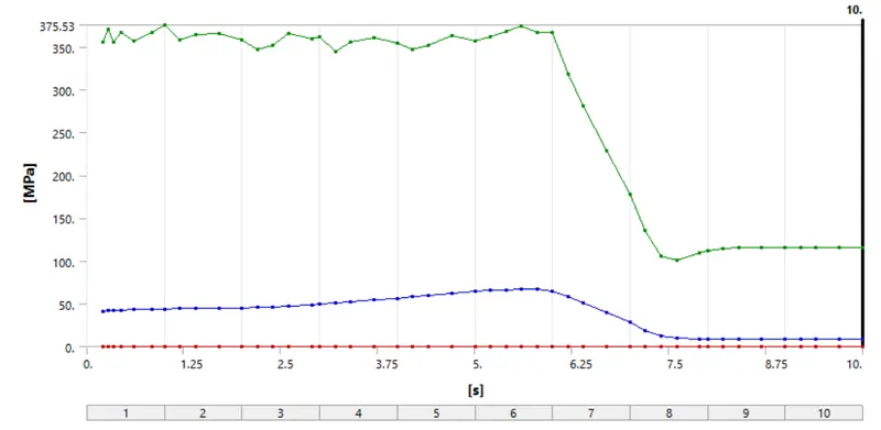
2. Equivalent von-misses stress:
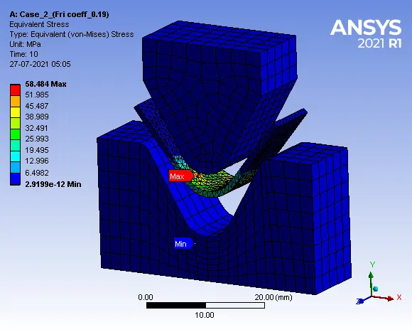
Maximum Stress = 58.484 MPa
- Stress Contours:
3. Equivalent Elastic Strain:
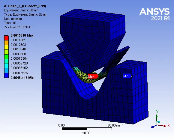
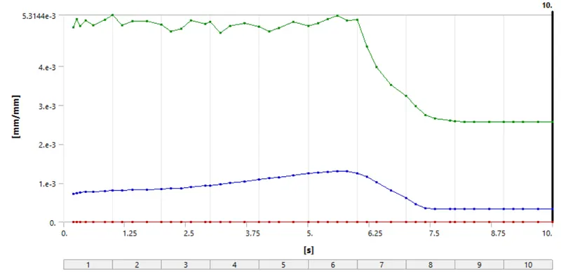
Maximum Strain = 0.0015818 mm/mm
- Strain Contours:
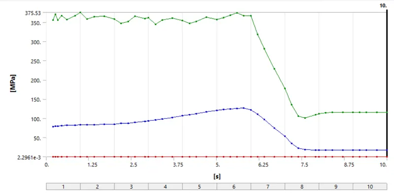
4. Equivalent Stress of Sheet:
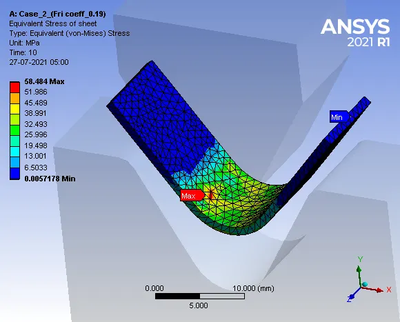
Maximum Stress = 58.484 MPa
- Stress Contours:
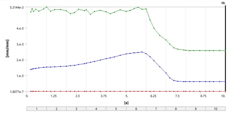
5. Equivalent Elastic strain of Sheet:
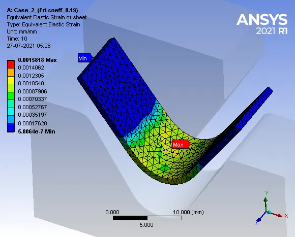
Maximum Strain = 0.0015818 mm/mm
- Strain Contours:
RESULT COMPARISON:
| S No. | Directional Deformation | Maximum Stress (MPa) | Maximum Strain (mm/mm) |
|
CASE 1 Frictional Coeff = 0.1 |
2.5052 mm | 57.506 MPa | 0.0015850 mm/mm |
|
CASE 2 Frictional Coeff = 0.19 |
2.2412 mm |
58.484 MPa |
0.0015818 mm/mm |
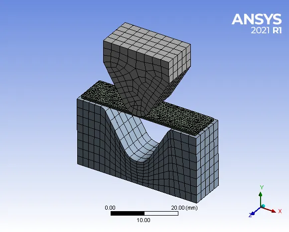
CASE 3: Refine the mesh on the plate With Aluminium alloy as material, run the analysis as in Case 1 and compare the results.
Meshed Model:
Details:
1. Punch and Die = 3mm
2. Sheet = 0.75 mm
- Method = Tetrahedrons
3. Face Sizing = 2mm
4. No of nodes = 22670
5. No. of elements = 10480
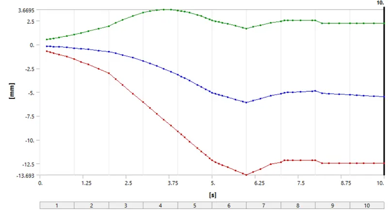
1. Directional Deformation:
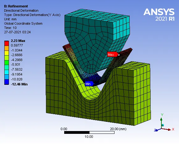
Maximum Deformation = 2.23 mm
- Deformation Contours:
2. Equivalent von-misses Stress:
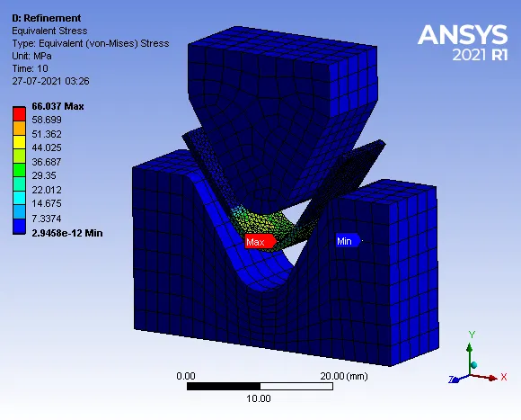
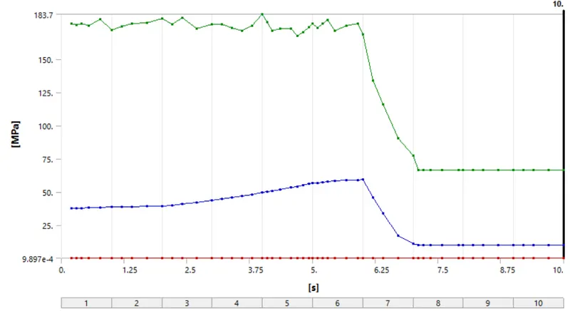
Maximum Stress = 66.037 MPa
- Stress Contours:
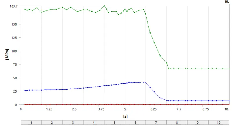
3. Equivalent Elastic Strain:
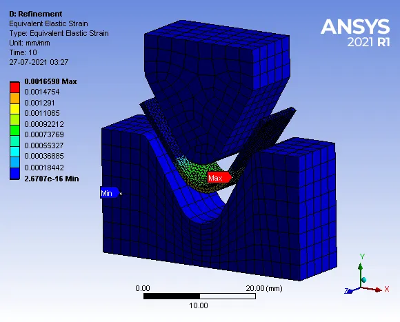
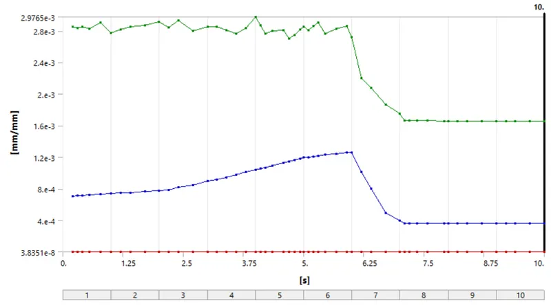
Maximum Strain = 0.0016598 mm/mm
- Strain Contours:
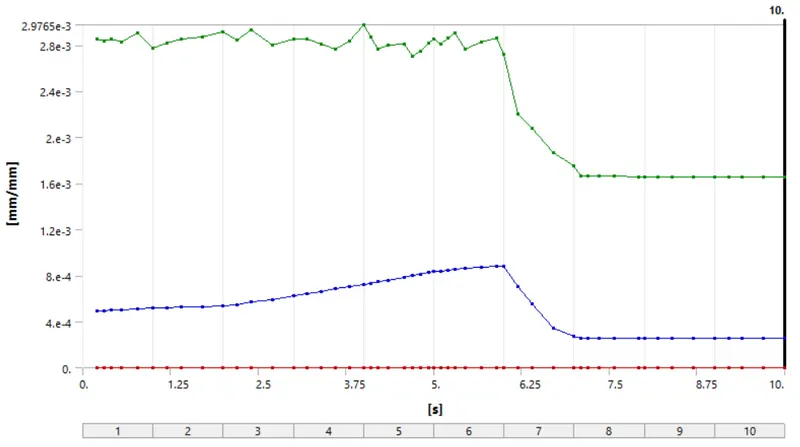
4. Equivalent Stress of Sheet:
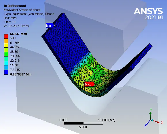
Maximum Stress = 66.037 MPa
- Stress Contours:
5. Equivalent Strain of Sheet:
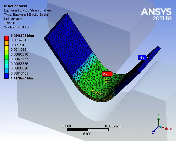 Maximum Strain = 0.0016598 mm/mm
- Strain Contours:
RESULT COMPARISON:
| S No. | Directional Deformation | Maximum Stress (MPa) | Maximum Strain (mm/mm) |
|
CASE 1(A) Mesh Size 1mm |
2.4185 mm |
57.506 MPa |
0.0015867 mm/mm |
|
CASE 3
|
2.2300 mm |
66.037 MPa |
0.0016598 mm/mm |
CONCLUSION:
Static structural analysis on sheet metal bending was performed for different sheet materials mentioned in the case study.
CASE 1 - Among the three materials used Aluminium alloy 1199 has the least amount of stress developed and Cu Alloy experienced maximum stress.
CASE 2 - With Aluminium alloy 1199 as material, Changing the frictional coefficient from 0.1 to 0.19 experiences more stress as compared to CASE 1, so the higher value of the coefficient of friction will result in a higher value of output.
CASE 3 - Refining the element size as 0.75mm and by performing a grid dependency test there will be a better approximation in the result. Using the optimized element size is better than that of further reducing the element size will consume more time and high cost