Week 3 Sheet metal Bending challenge
Understanding the effect of static structural analysis on a sheet metal:
Aim:-
To study and perform structural analysis on a sheet metal with different material and frictional coefficient. Grid dependency test was also performed to optimize the element size for better accuracy.
- Case 1: Aluminium Alloy 1199, Copper alloy NL and Magnesium alloy NL
- Case 2: With the material as Aluminium Alloy, change the friction coefficient to 0.19
- Case 3: With Aluminum alloy as material, changing the mesh size.
Analysis Set-up for Sheet metal:-
Case 1:-
I. Geometry:-
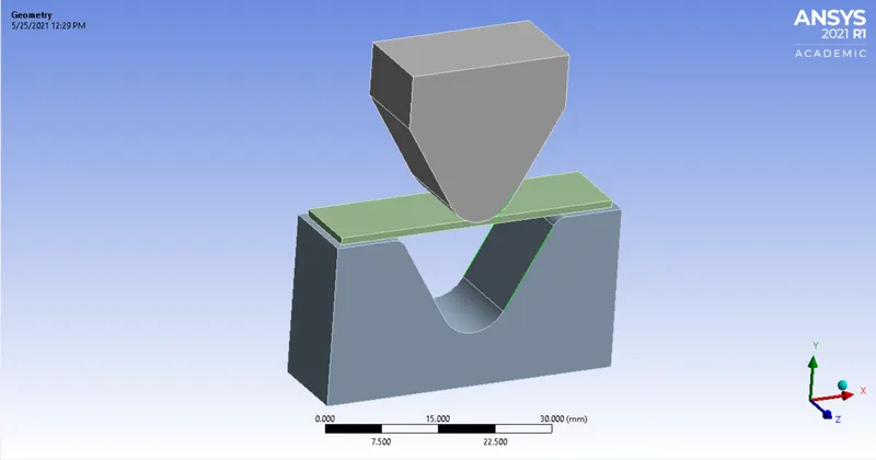
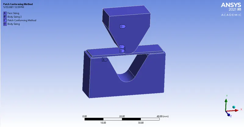
The CAD model of sheet metal is imported in Ansys static structural environment. It comprises of three different components named as Punch, Die and Sheet. It is based on working principle that when the die will have applied force on top, then the sheet gets bend across the die and for that the punch and die would move in backward direction, after the sheet metal bending occurs.
II. Materials:-
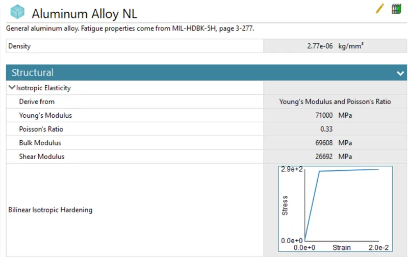
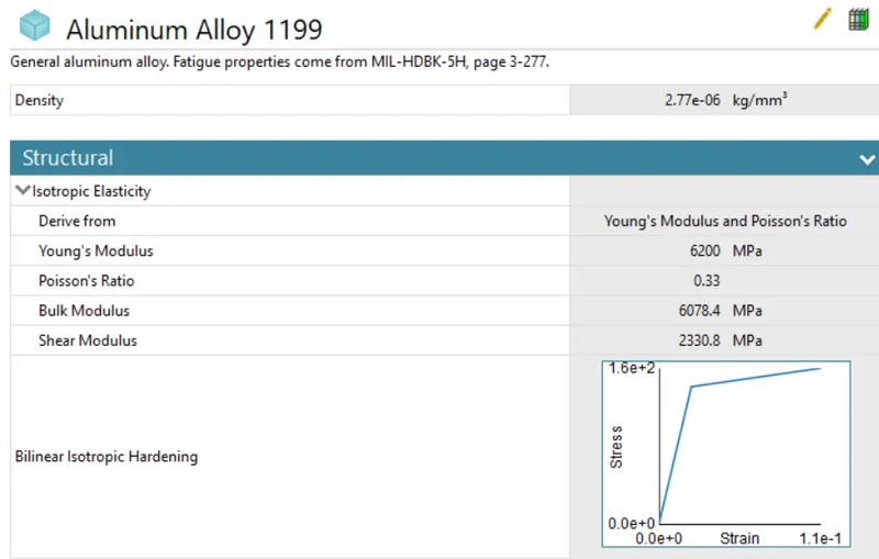
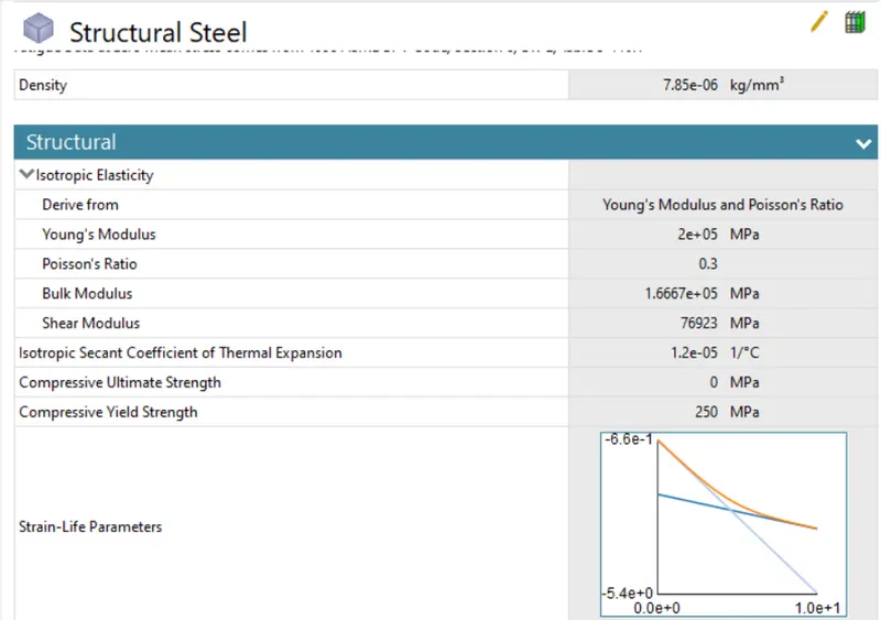
Below are the materials which is used to perform analysis for the sheet metal. The analysis is carried out for each material individually.
Case 1: Plate and Die (Structural Steel)
Phase 1: Sheet (Aluminium Alloy 1199)
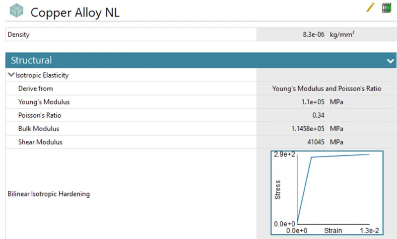
Phase 2: Sheet (Copper Alloy NL)
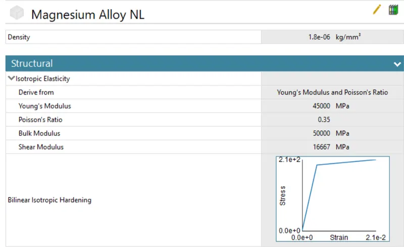
Phase 3: Sheet (Magnesium Alloy NL)
Case 2 and 3: Sheet (Aluminium Alloy NL)
Non-linear materials are considered to account for the regions of plastic deformation. The detailed engineering data for each material are as shown below:
III. Connection Details:-
Contact Details:
1. Frictional- Punch to Sheet:
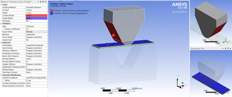
Frictional contact is given below between faces of punch and sheet as shown in the image below. The 3 faces of punch came in contact with 1 face of sheet with a frictional coefficient of 0.1. Then the behaviour of geometry is changed to Asymmetric and then the formulation is changed to Augmented Lagrange. Also, normal stiffness factor of 0.1 is assigned to the contact faces. Lastly, interface treatment in geometric modification is assigned as 'Add offset, Ramped effects.'
2. Frictional- Sheet to Die:
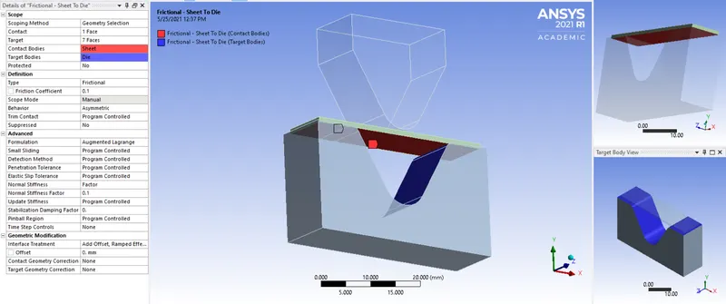
Frictional contact is given below between faces of sheet and die as shown in the image below. The 1 face of sheet came in contact with 7 faces of die with a frictional coefficient of 0.1. Then the behaviour of geometry is changed to Asymmetric and then the formulation is changed to Augmented Lagrange. Also, normal stiffness factor of 0.1 is assigned to the contact faces. Lastly, interface treatment in geometric modification is assigned as 'Add offset, Ramped effects.'
IV. Mesh:-
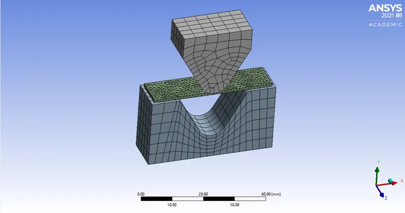
1. The sheet metal and faces of punch and die which come in contact with sheets are alone meshed with an element size of 2 mm other part are meshed with an element size of 4 mm.
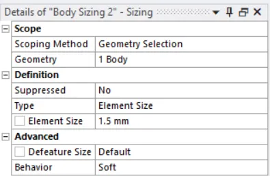
2. For Case-3, the sheet metal and the face of punch and die which come in contact with sheet are alone meshed with an element size of 1.5 mm, the sheet metal element are of tetrahedrons type.
3. At this type, the fine mesh is generated which is sufficient to carry out simulation which gives desired results.
V. Boundary Conditions and Analysis Settings:-
1. Analysis Settings:-
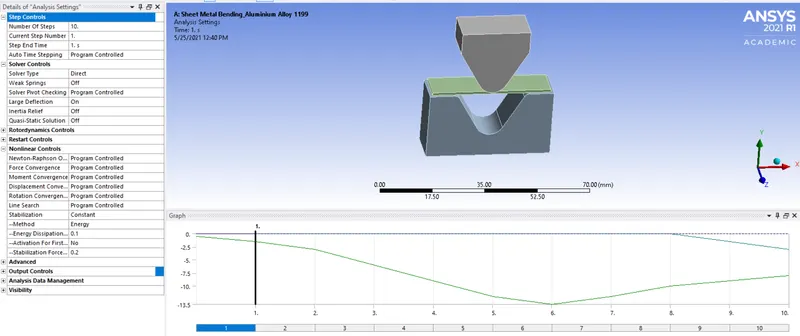
For this analysis the number of steps is set to 10 with Auto Time stepping is program controlled. After that, the solver type is to be Direct and then Large deflection is set to On, so as to account for change in stiffness due to change in shape of gears. Lastly, the stabilization is said to be constant and method as energy. the energy disspiation is said to be 0.1.
2. Displacement Load:-
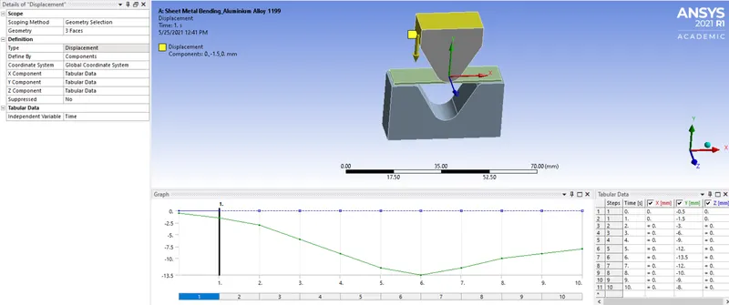
- Displacement 1 load:- (On punch to Y-axis)
Basically, we have to select the faces on punch as geometry. Then, its type is considered as displacement and then its Y axis get's value from tabular form. Then, its value is ploted around graph.
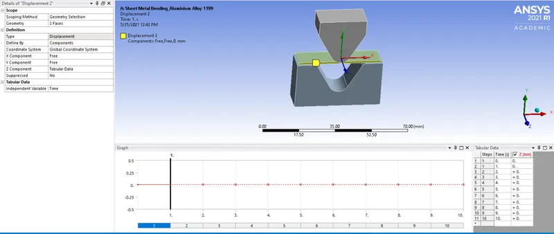
- Displacement 2 load:- (On sheet to Z-axis)
Basically, we have to select the faces on sheet as geometry. Then, its type is considered as displacement, but here sheet is fixed around Z-axis. Then, its value is ploted around graph.
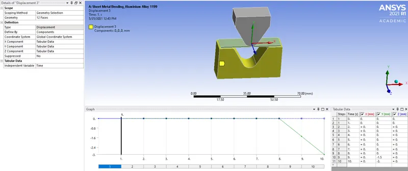
- Displacement 3 load:- (On Die to Y-axis)
Basically, we have to select the faces on die as geometry. Then, its type is considered as displacement and then its Y axis get's value from tabular form. When the punch is applied load and when the sheet metal gets bend, then the die should move backwards along the direction. Then, its value is ploted around graph.
VI. Post-processing and Results:-
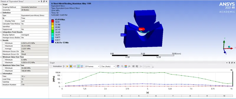
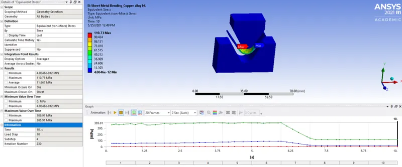
In this analysis the punch and die displacement is given as boundary conditions, therefore it can be expected as that the displacement and strain would be the same for all the three materials in the linear region. It should be expected that stress will vary depending on the material stiffness and yield strength. The higher material exhibit higher stress. Then, the analysis is performed to Equivalent stress, Directional deformation, and equivalent elastic strain for the materials Aluminium Alloy 1199, Copper alloy NL, Magnesium alloy NL.
1. Equivalent stress:-
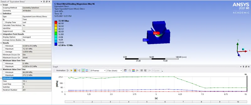
Aluminium Alloy 1199 Copper Alloy NL Magnesium Alloy NL
2. Equivalent Elastic Strain:-
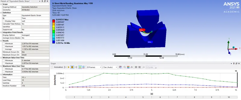
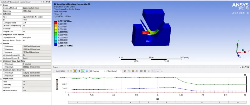
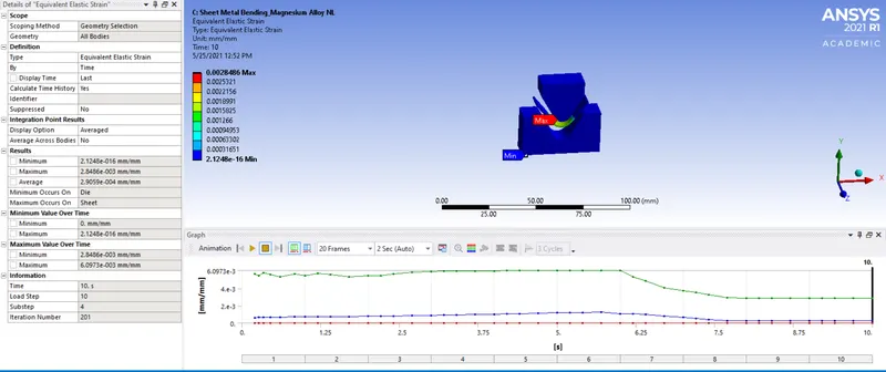
Aluminium Alloy 1199 Copper Alloy NL Magnesium Alloy NL
3. Directional Deformation:-
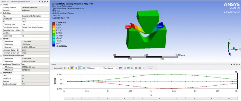
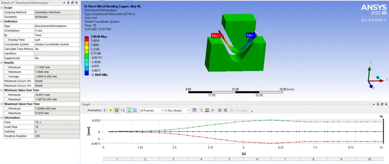
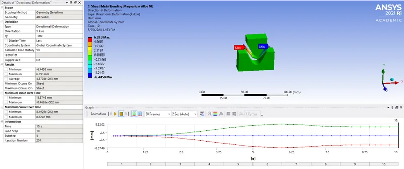
Aluminium Alloy 1199 Copper Alloy NL Magnesium Alloy NL
VII. Post processing Results Summary:-
|
Parameters |
Aluminum Alloy 1199 |
Copper Alloy |
Magnesium Alloy |
|
Equivalent stress (Max) |
43.414 MPa |
110.73 MPa |
72.181 MPa |
|
Equivalent stress (Min) |
4.3631e-012 MPa |
4.0046e-012 MPa |
4.5381e-012 MPa |
|
Directional deformation(Max) |
2.2618 mm |
7.0646 mm |
6.393 mm |
|
Directional deformation(Min) |
-2.3674 mm |
-7.1845 mm |
-6.4458 mm |
|
Equivalent elastic strain(Max) |
1.0517e-002 mm/mm |
1.7821e-003 mm/mm |
2.8486e-003 mm/mm |
|
Equivalent elastic strain(Min) |
2.2975e-016 mm/mm |
2.6663e-016 mm/mm |
2.1248e-016 mm/mm |
Case 2:- With the material as Aluminium Alloy, change the friction coefficient to 0.19
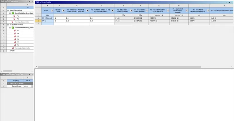
The frictional coefficient will have an impact on the punch force needed and therefore it is useful to keep it as low as possible. The contact tool is used to obtain the frictional stress between the two aforementioned contacts.
As the frictional coefficient increases, equivalent stress and equivalent strain decreases and directional deformation increases, as we can see it in above table.
Case 3:- With Aluminium alloy as material, changing the mesh size
I. Mesh:
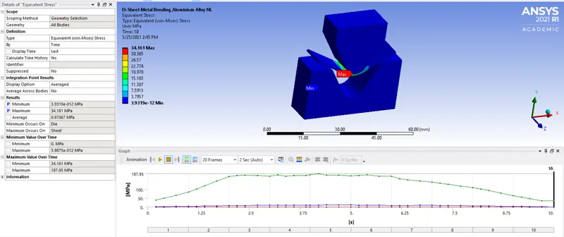
II. Equivalent stress:
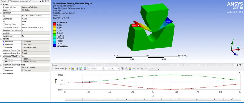
III. Directional deformation:
IV. Equivalent elastic strain:
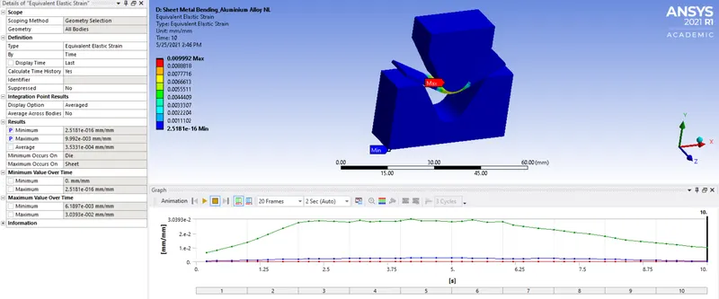
As the mesh gets finer, the result will become more accurate. From the above table, we can see that mesh gets finer the results are going to be more accurate.
V. Summary:
|
Parameters |
Aluminum Alloy NL |
|
Equivalent stress (Max) |
34.161 MPa |
|
Equivalent stress (Min) |
3.9319e-012 MPa |
|
Directional deformation(Max) |
2.1681 mm |
|
Directional deformation(Min) |
-2.2045 mm |
|
Equivalent elastic strain(Max) |
9.992e-003 mm/mm |
|
Equivalent elastic strain(Min) |
2.5181e-016 mm/mm |
Conclusion:-
Case 1: Among the three materials used Aluminium alloy 1199 has the least amount of stress is developed.
Case 2: With Aluminium alloy 1199 as material, changing the frictional coefficient from 0.1 to 0.19 doesn't affect the results.
Case 3: With Aluminium alloy 1199 as material, increasing the mesh size from 1 to 1.5 mm doesn't affect the results.