Week 3 - Pitot tube
Week 3 - Pitot Tube
In aviation, the most common technique for determining an aircraft's airspeed, Mach number, altitude, and altitude trend is a pitot-static system, which consists of pressure-sensitive equipment. A static port, pitot tubes, and pitot-static instruments are the standard components of a pitot-static system. Air data computers, flight data recorders, altitude encoders, cabin pressurization controls, and different airspeed switches are other instruments that could be fitted. Since the data gathered from the pitot static system, such as altitude, may be safety-critical, errors in pitot-static system readings can be exceedingly harmful. Pitot-static system failure has been linked to a number of commercial airline catastrophes.
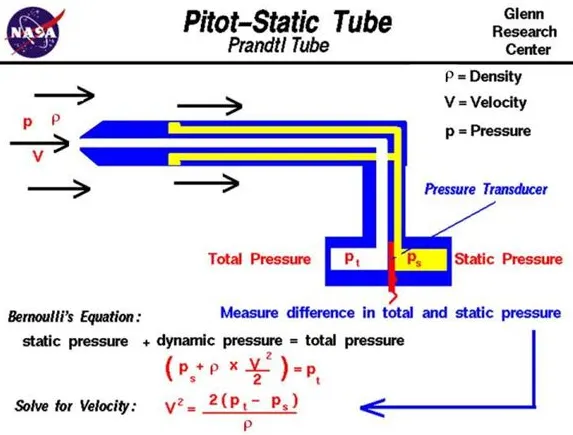
A schematic illustration of a pitot tube is displayed on this page. Aircraft speedometers are made of pitot tubes. The aircraft's real tube measures about 1/2 inch (1 centimetre) in diameter and 10 inches (25 centimetres) in length. A centre hole is drilled down the tube's axis, then numerous tiny holes are bored all the way around the tube. One side of an apparatus known as a pressure transducer is connected to the external holes. The tube's centre hole, which connects to the transducer's opposite side, is kept apart from the holes on the outside.
Using an electronic strain gauge to measure the strain in a thin element, the transducer calculates the difference in pressure between the two sets of tubes. The pitot tube is installed in the airplane such that the outside holes are perpendicular to the centre tube and the centre tube is always pointing in the direction of movement. (On certain aircraft, the pitot tube is mounted atop a longer boom that protrudes from the wing or the aircraft's nose.
Procedure:
A mesh file of the pitot static tube is imported to Fluent and then the solver parameters are defined.
For the first case, the solver preferred is Density based as of the velocity being 240 m/s, for the rest cases Pressure Based solver is used.
CASE 1:
v = 240 m/s, p = -2817 Pa
The Inlet velocity is kept 240 m/s, with Gauge pressure of -2817 Pa and the same value of pressure is used in outler boundary condition.
For the pitot tube surface, the wall condition is assigned.
The Reference values are to be calculated for the 'inlet' and the operating pressure is set to zero.
Following is the computed data for the first case,
Contours of Static Pressure, Total Pressure and Velocity
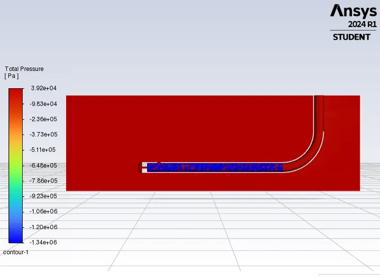
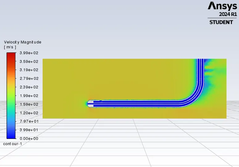
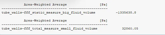
Static pressure `(Ps)`= -1335638.8 Pa
Total Pressure `(Pt)` = 32860 Pa
So velocity, `v = sqrt((2*(Pt-Ps))/rho)`= 1494 m/s
CASE 2:
v = 100 m/s, p = 33287 Pa
Following is the computed data for the second case,
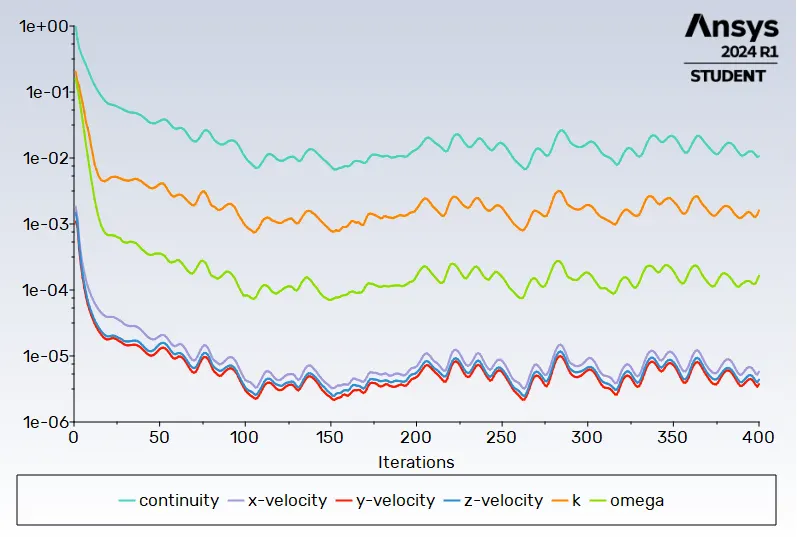
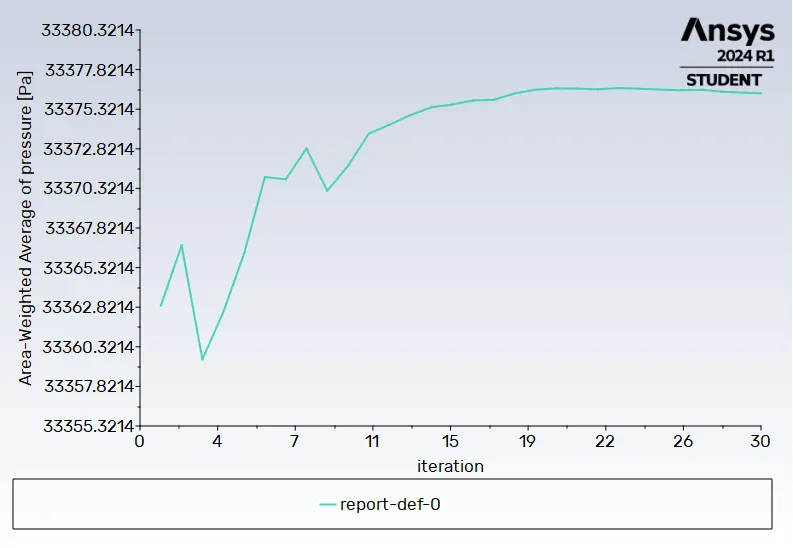
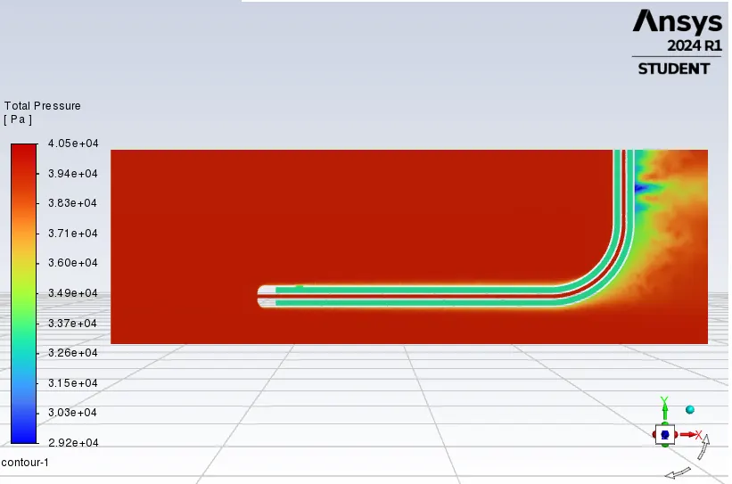
Contours of Static Pressure, Total Pressure and Velocity
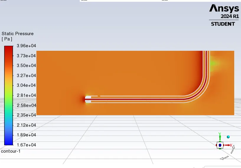
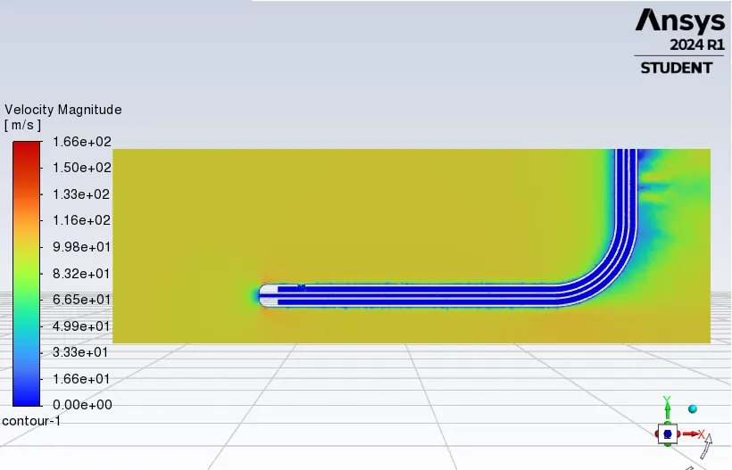

Static pressure `(Ps)`= 33374.056 Pa
Total Pressure `(Pt)` = 39504 Pa
So velocity, `v = sqrt((2*(Pt-Ps))/rho)`= 100.040 m/s
The value of velocity is in the acceptable range with minor error.
CASE 3:
v = 62 m/s, p = 65780 Pa
Following is the computed data for the third case,
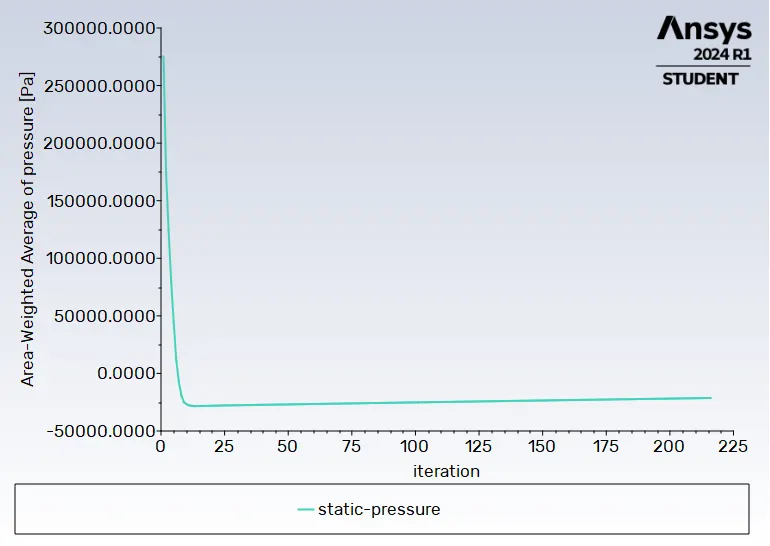
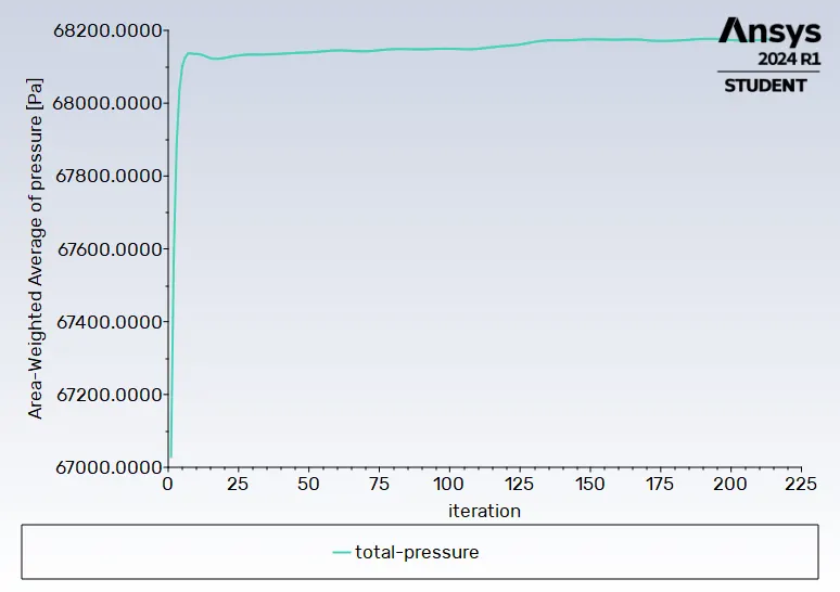
Contours of Static Pressure, Total Pressure and Velocity
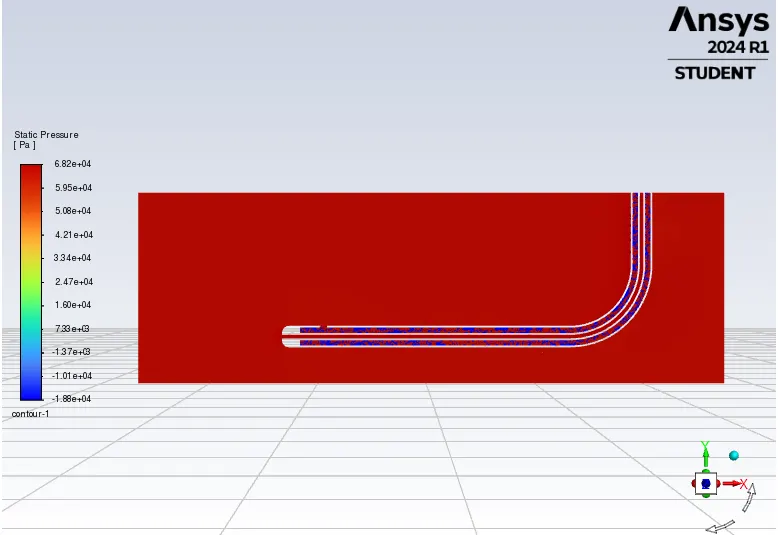
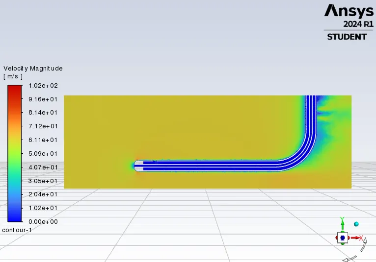

Static pressure `(Ps)`= -18747.892 Pa
Total Pressure `(Pt)` = 68178.198 Pa
So velocity, `v = sqrt((2*(Pt-Ps))/rho)`= 376 m/s