Week 3- Geometry cleanup and Mid-surfacing
Answers:
Aim: To extract mid-surface for the tube model and provide a connection with a sharing option at the tube joint locations by using ANSYS SpaceClaim
Case1:
Procedure: Import the tube joint model to the SpaceClaim graphical window
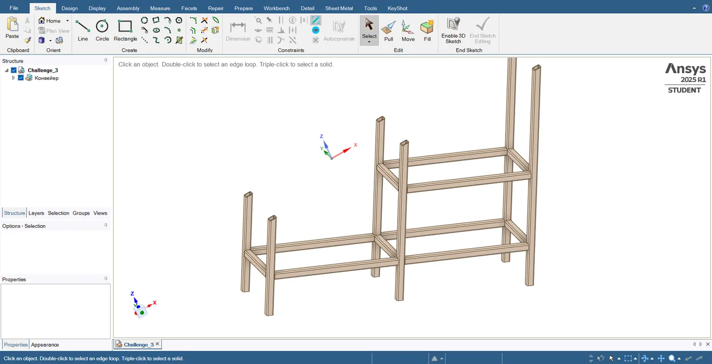
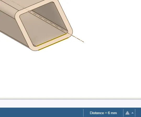
Measure the thickness
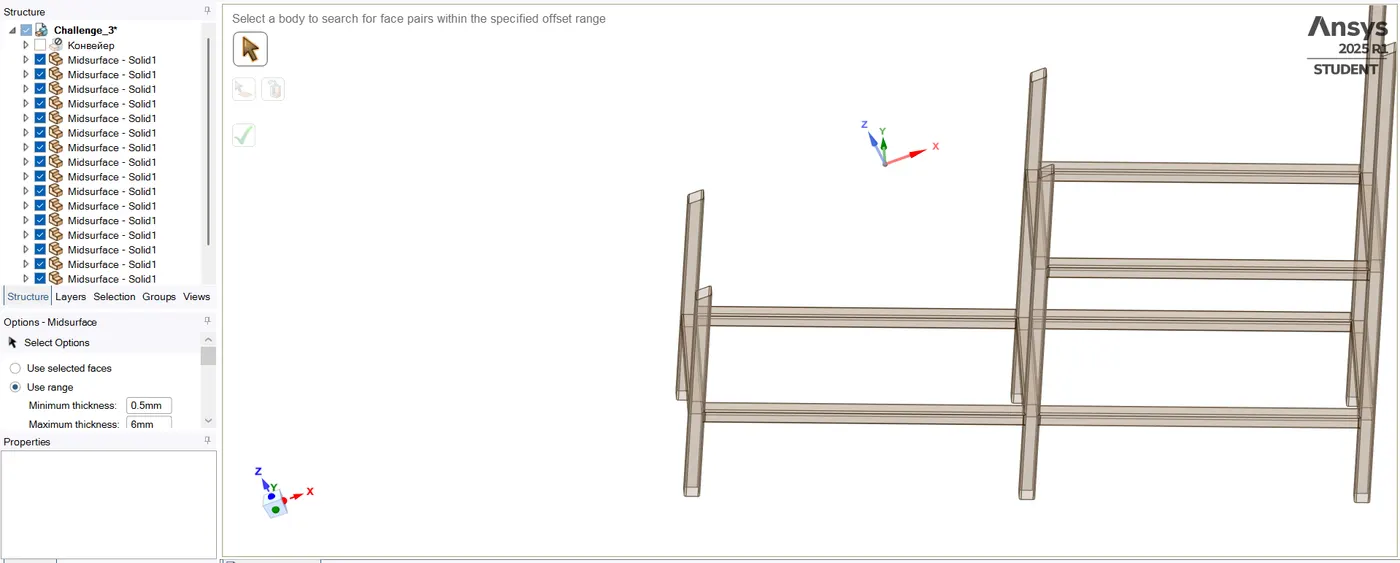
Mid Surfacing:
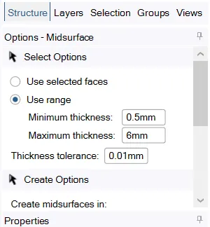
Next, extract the mid surface for the tube joint by using the face option or by using a range i.e 0 to 6mm
Prepare>>Midsurface>> Use range 0 to 6mm
Extend
Next, extend the tube to have a proper connection
Prepare>>Extend
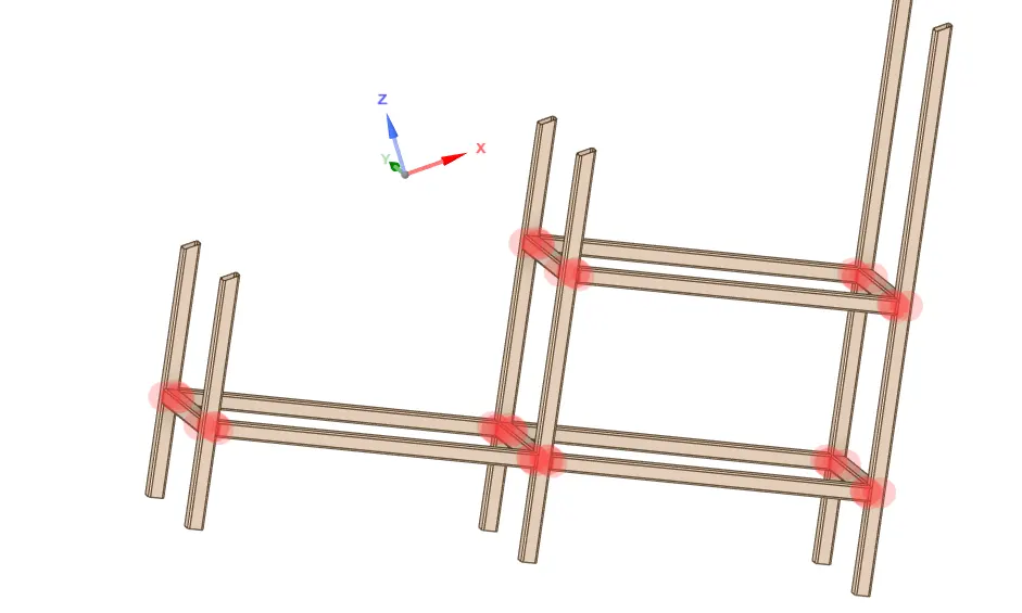
Next, provide a connection with a sharing option at the tube joint locations by using the share option
workbench>>share
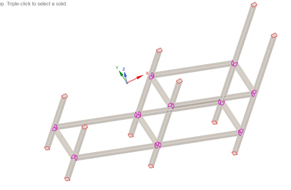
Conclusion:
Hence extracted the mid-surface for the given component.
Learning outcomes
Learned to extract mid-surface, the extension of the surface, and connection surfaces.
CASE2
Aim: To perform a modal analysis to verify connections and analyze the results for the blocks created in the SpaceClaim
Procedure:
In the ansys workbench select Analysis system and then choose Modal analysis and then create a Modal A
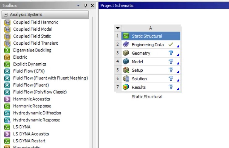
Next, click on the geometry and select spaceclaim.
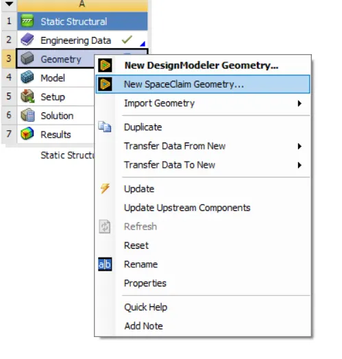
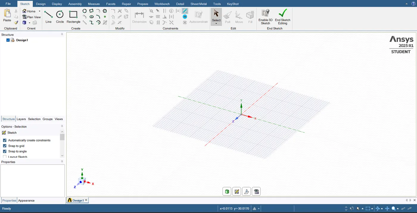
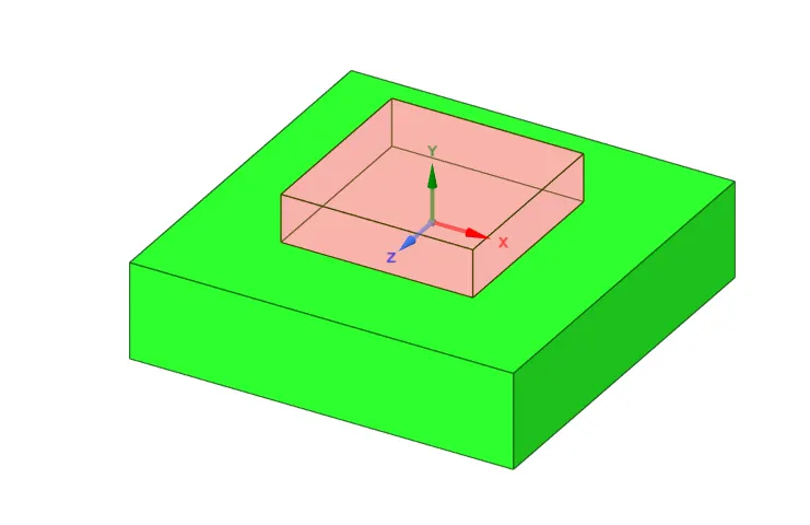
Now create a rectangle of the given dimensions of 40mm*40mm*10mm
note: check the 'Define rectangle from center' option
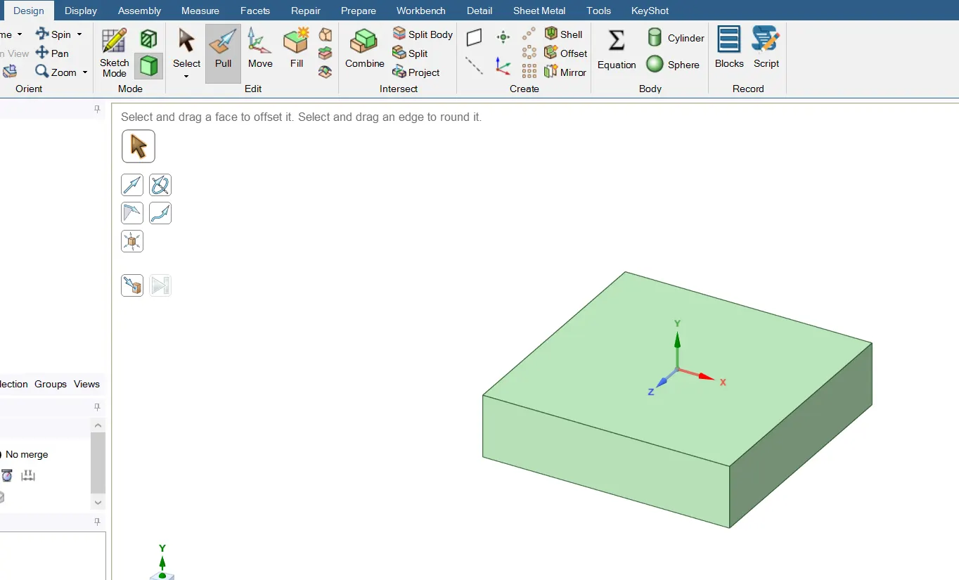
Goto >> Design >> Pull >> pull the rectangle 10mm
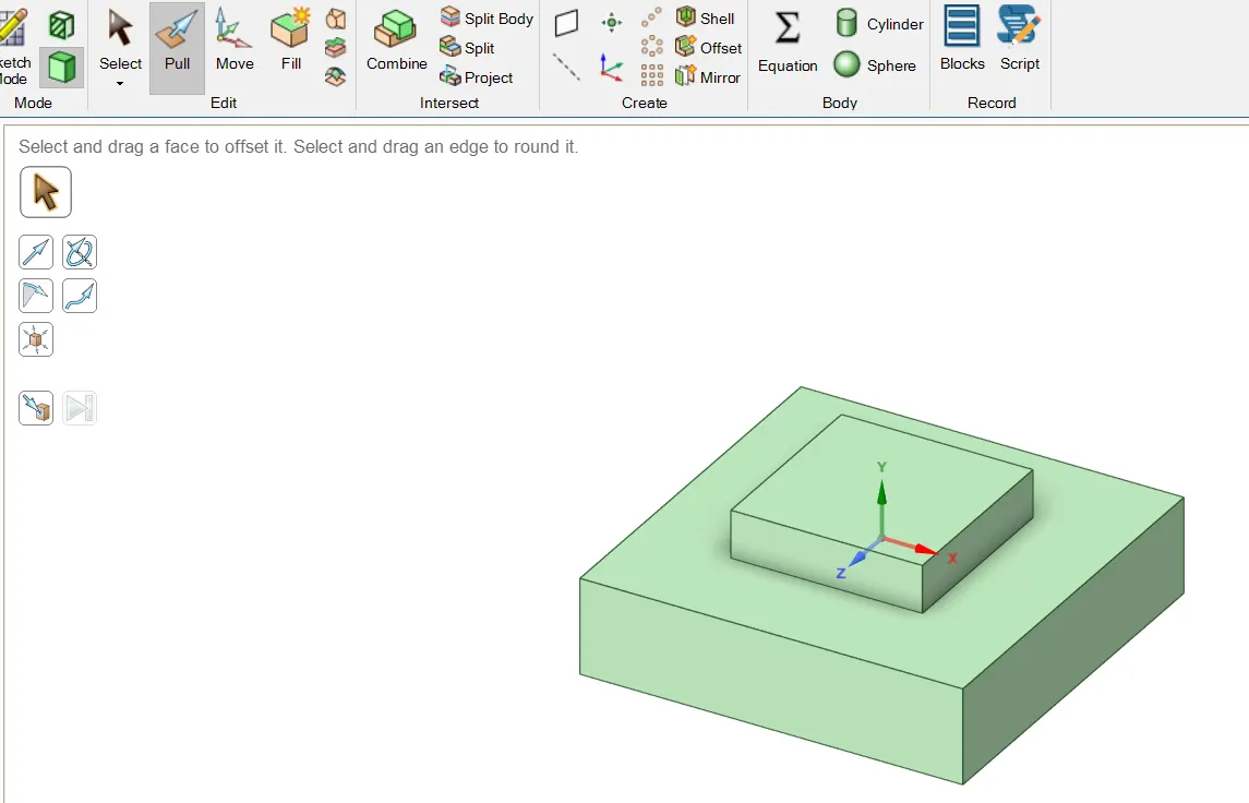
Now follow the similar steps for a rectangle of dimension 20mm*20mm*5mm
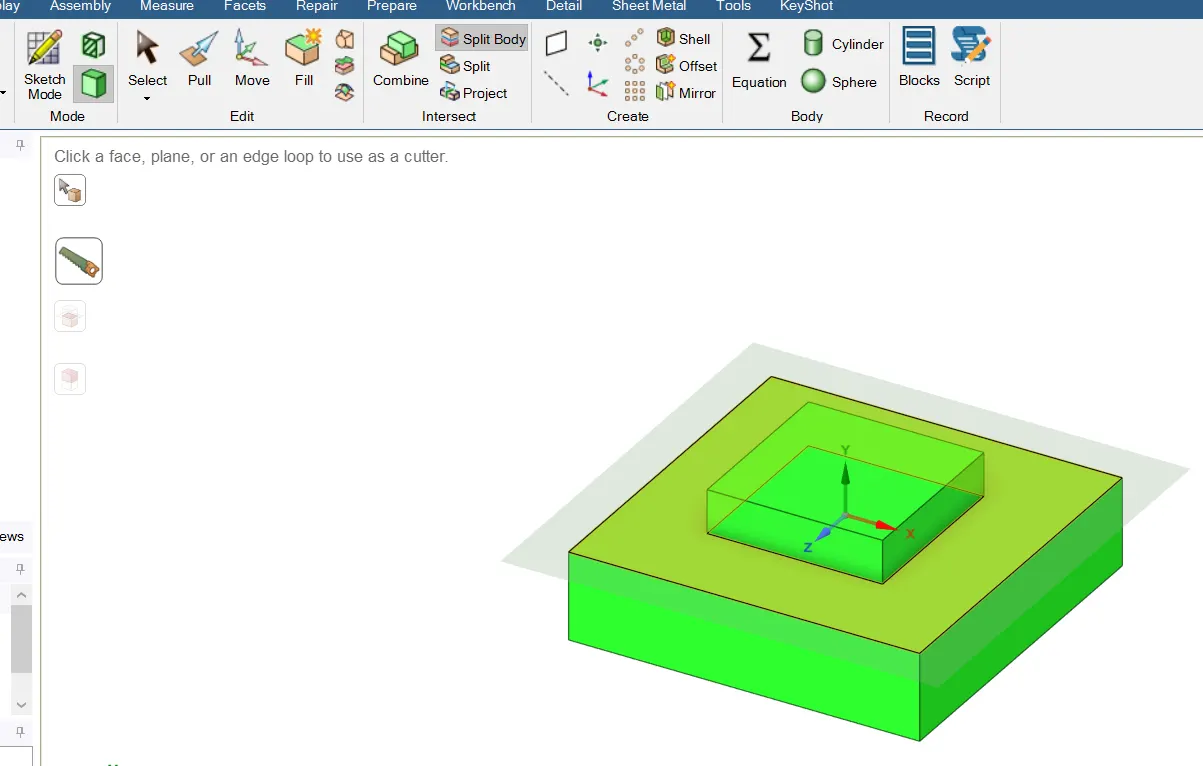
Next, split the blocks by using the split body option
Design >>SplitBody
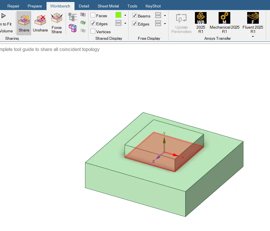
Share Topology between the two blocks by using the workbench
workbench>>share
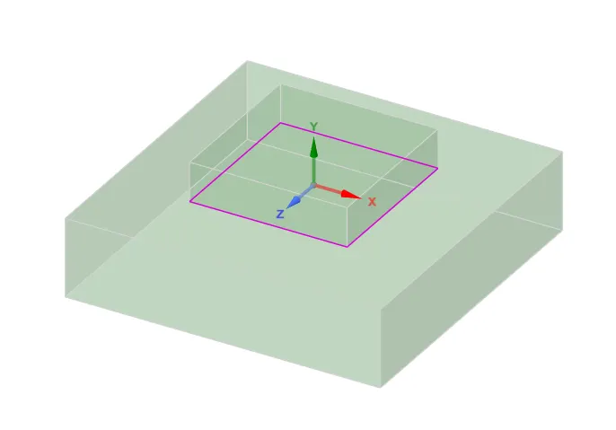
After creating the model in SpaceClaim next go to ansys workbench select Modal, select the model and then edit to open ansys mechanical
Ansys workbench>>Modal>>Model>>edit or update>>Mechanical
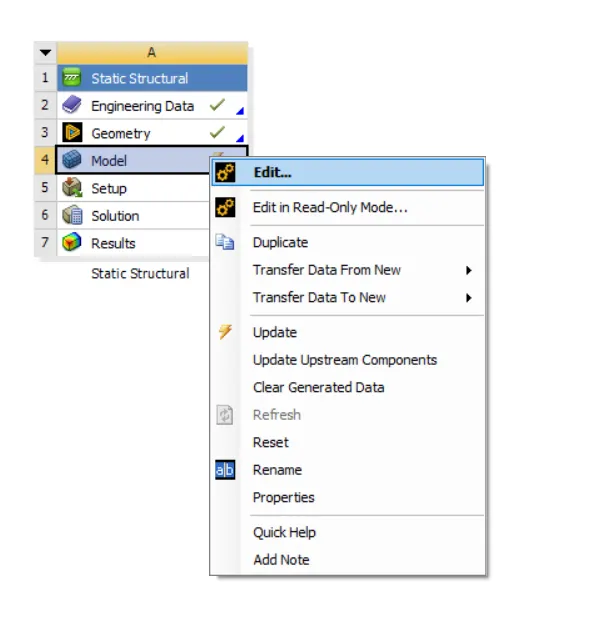
Then geometry will be updated in the ansys Mechanical
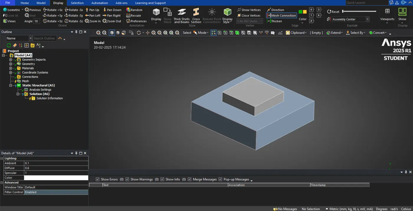
To mesh the blocks the following steps are.
In ansys mechanical > project tree > mesh > method > automatic method > selected the geometry > Hex dominant method > done.
Project tree > mesh > Sizing > selected the geometry > element size-2.5 mm > done.
Project tree > mesh > generate mesh > meshed the blocks as shown below,
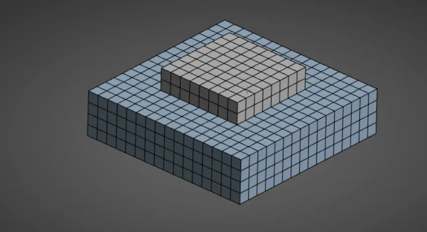
To provide the fixed support for the bottom face of Block B in the following steps.
Project tree >Modal > fixed support > selected the bottom face of Block B > fixed it.
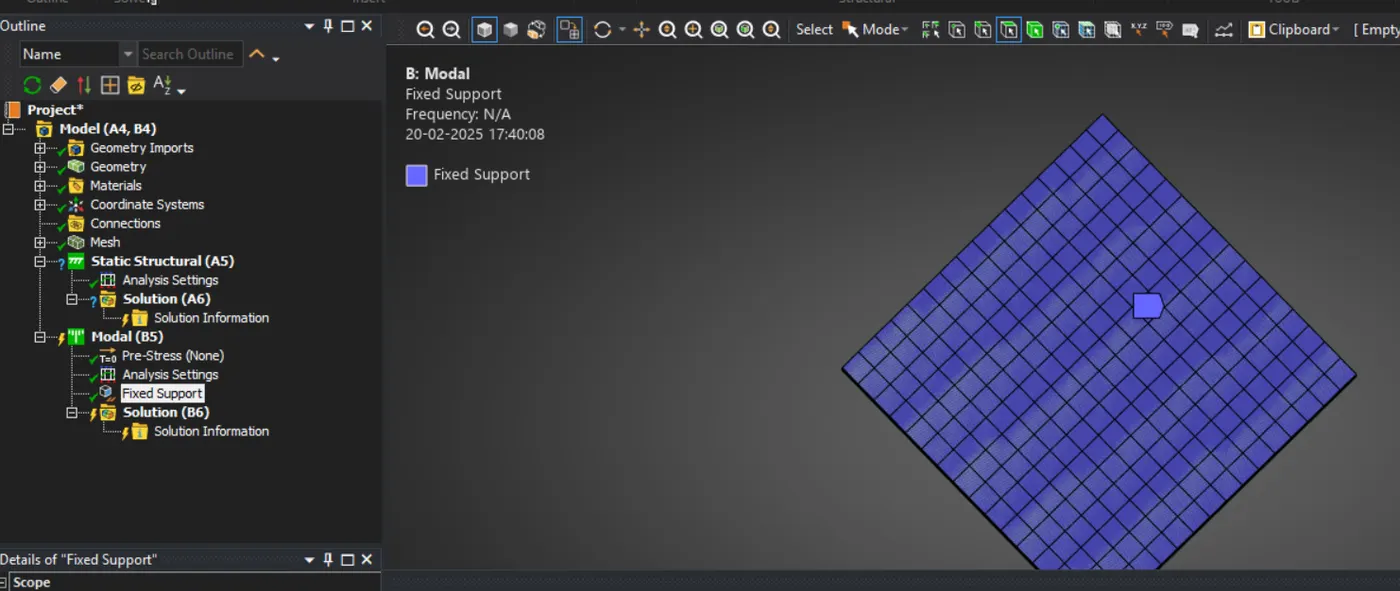
Set the modal analysis settings by the following steps.
Project tree > Modal > analysis settings > max modes to find is 10 >done.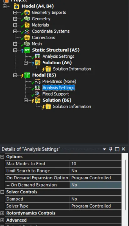
solve the problem by the following steps.
Project tree > Modal > solution > solve
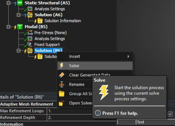
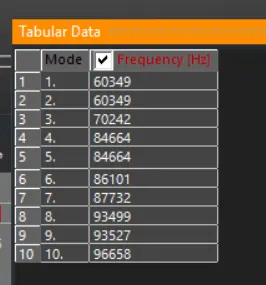
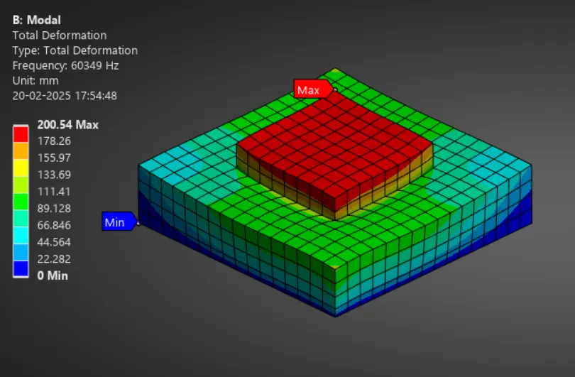
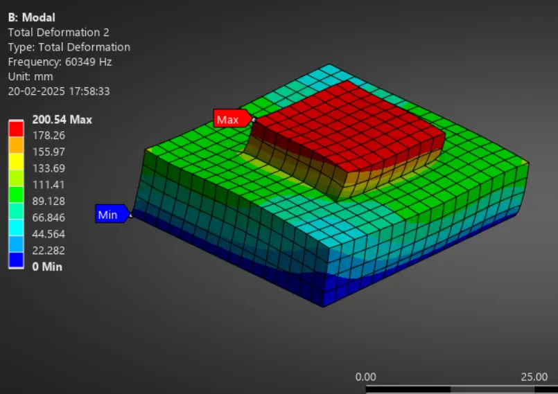
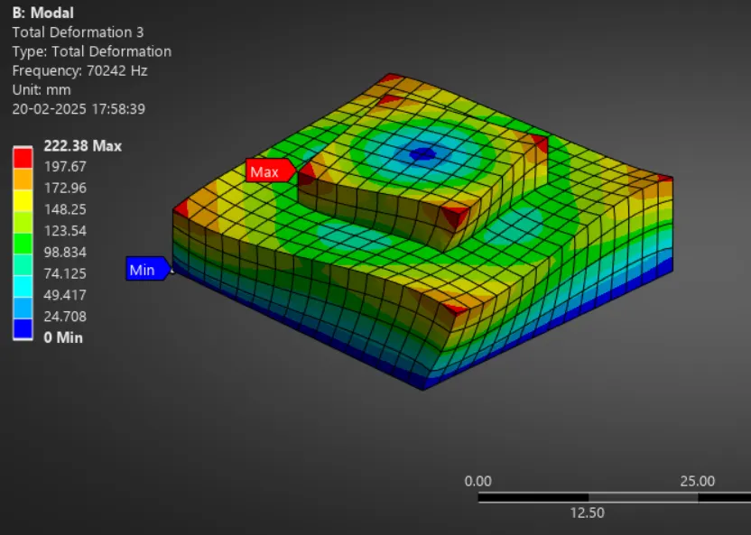
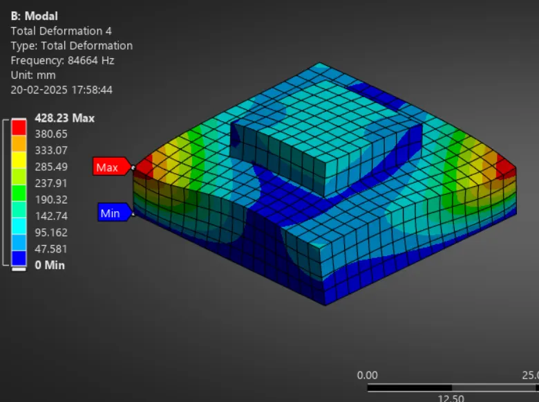
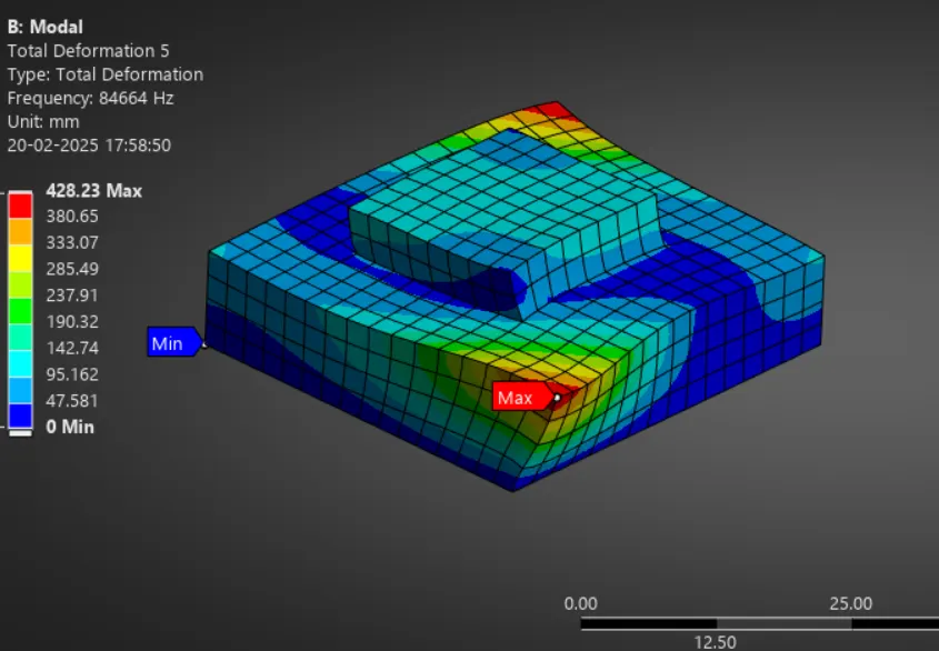
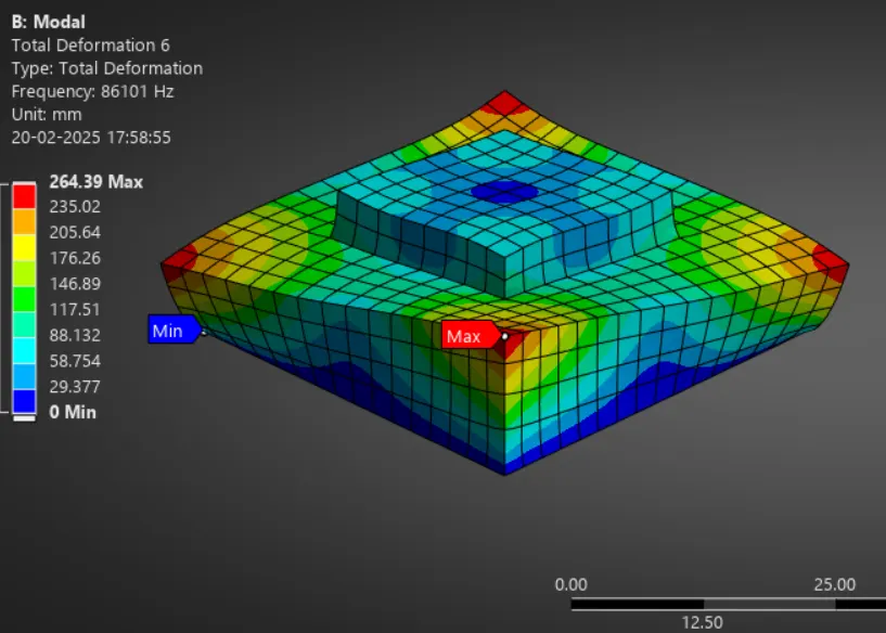
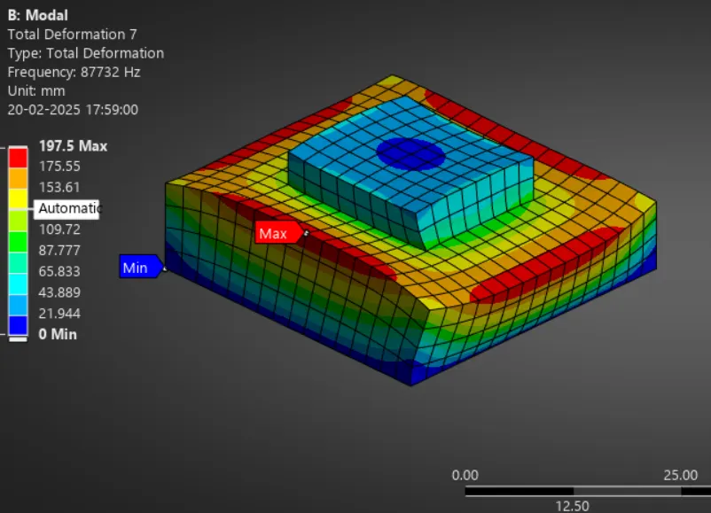
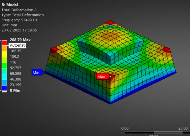
Get the modeshape results by the following steps.
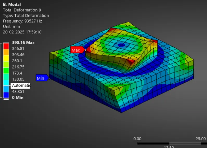
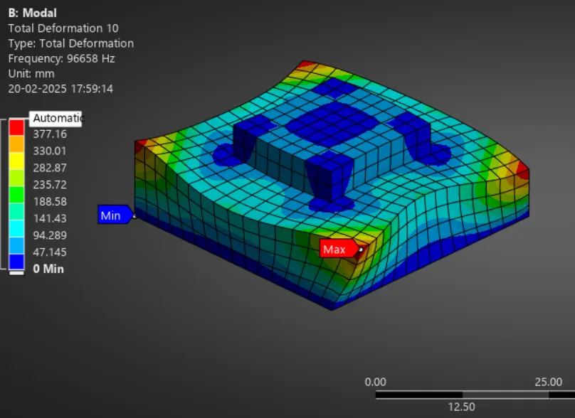
The data was selected in the frequency table > RC > Create mode shape results from the total deformation >done.
Then Project tree > solution > RC > evaluate all results.
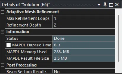
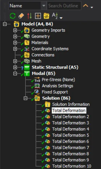
Learning outcome:
Learned to create a geometry in the space claim
Learned to assign engineering data, meshing, and Modal Setup in ansys workbench
Conclusion: Mode shapes, total deformation, and its related frequency have been found by using Modal analysis.