Week 3: Flow over a backward facing step
Objective:
Once you have watched the video, setup the case in CONVERGE
Once you have the base setup ready, run the case for three different base mesh sizes
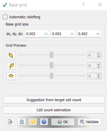
- dx = dy = dz =2e-3 m
- dx = dy = dz =1.5e-3 m
- dx = dy = dz =1.0e-3 m (If this is too much for your PC, use 1.2e-3 m)
Post process your results and document your findings in https://projects.skill-lync.com/
Contents to be shown in the report:
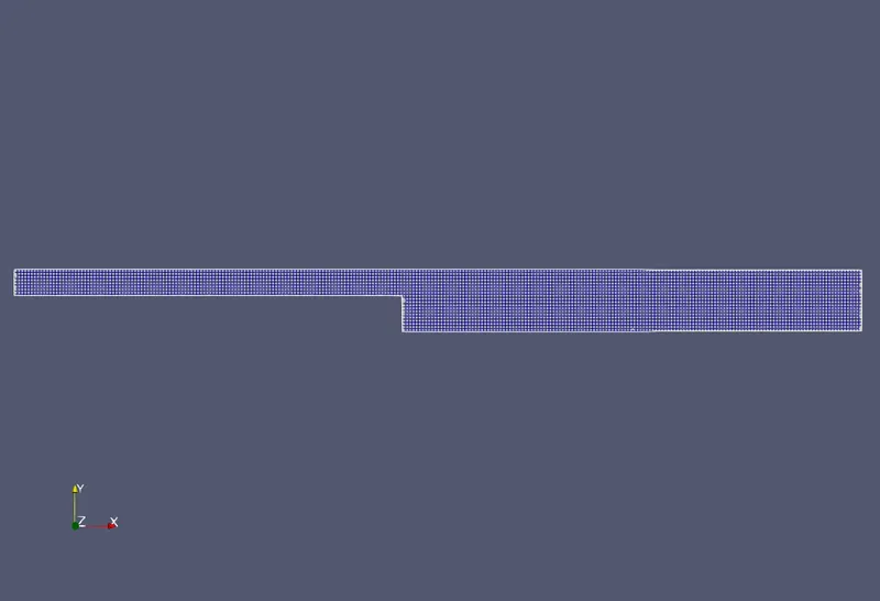
1. Show the mesh (i.e surface with edges) for all the 3 base mesh sizes
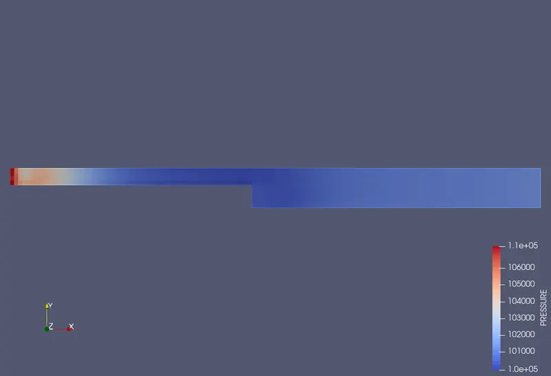
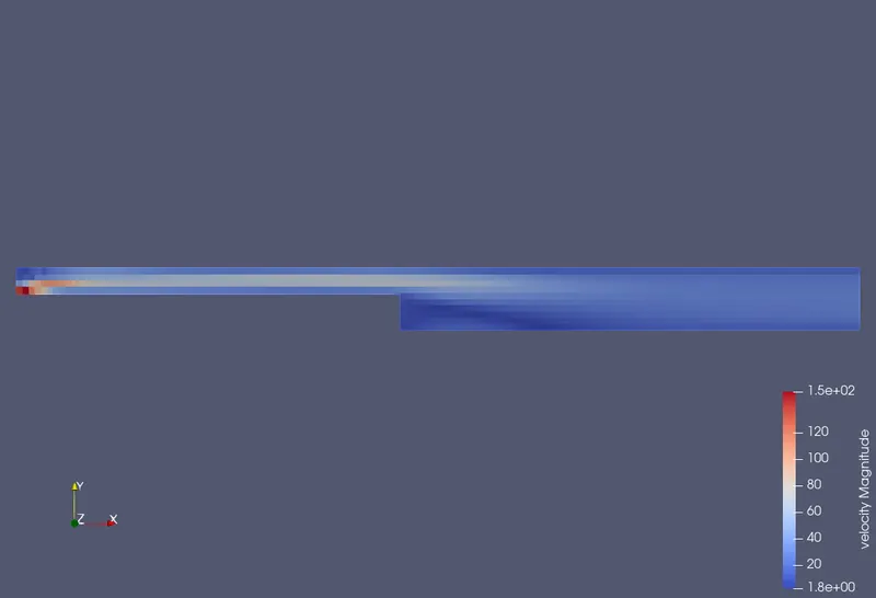
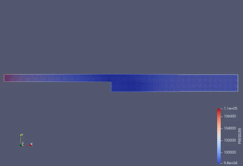
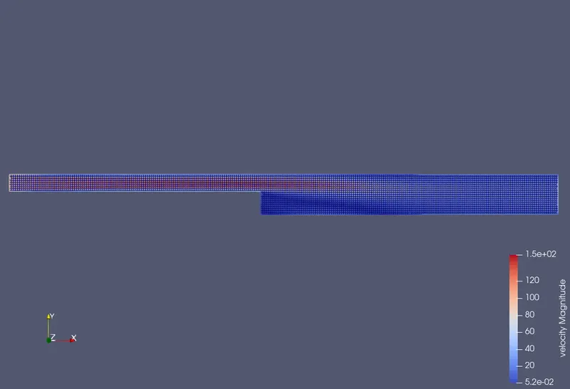
2.Show pressure and velocity contours
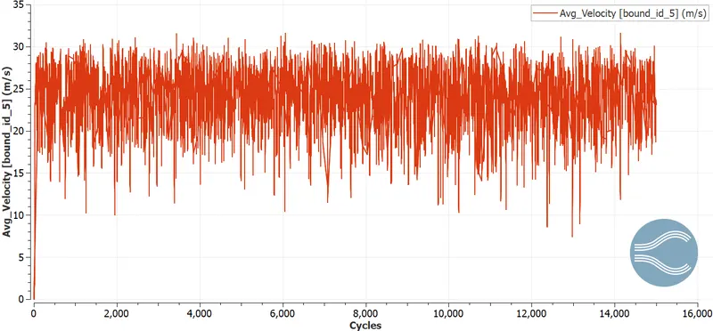
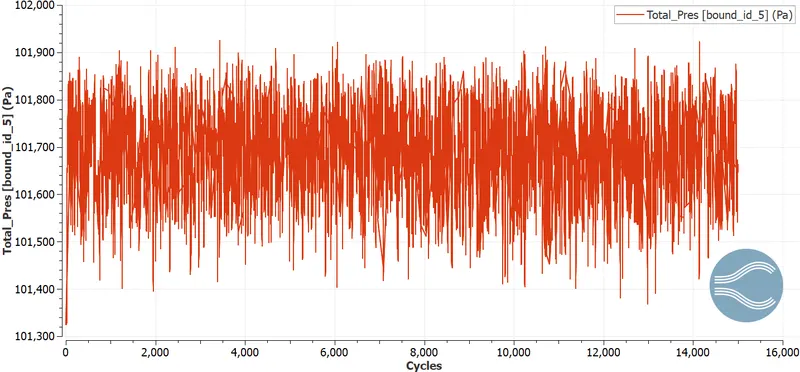
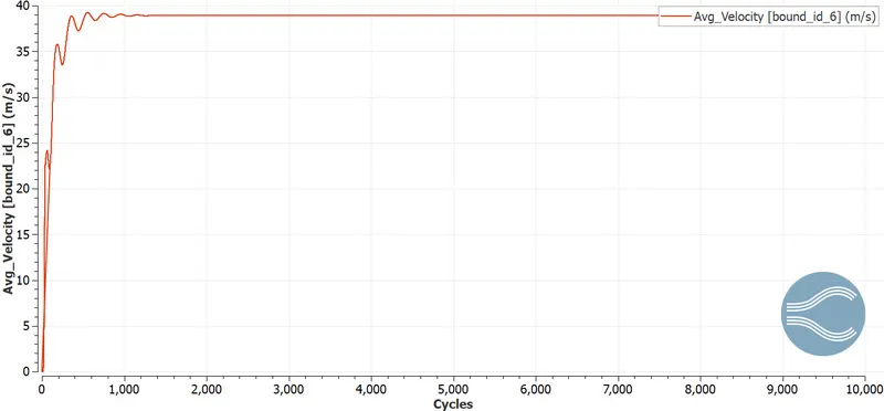
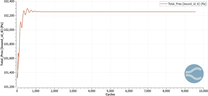
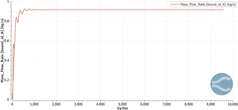
3. Show the plots of velocity, pressure, mass flow rate and total cell count for all the 3 base mesh sizes
4. Also explain where and why separation is taking place in detail.
Answer:
About Flow Seperation
Due to the adverse pressure gradient, might be because of sharp edge or circular profile, a flow suppose moving in one direction faces backward pressure that results in loss of momentum of the flow. And a continuous attack of this adverse pressure gradient impels the flow to detach from the surface resulting in flow seperation. Due to this detachment & adverse pressure gradient, the flow tends to move in the backward direction causing the flow to reverse at the seperated region which is known as wake region as well.
Input Geometry
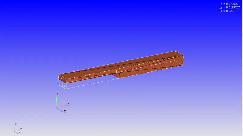
Normals have been checked to make sure, it is facing inside the box as the fluid is going to flow through inside the model.
Boundary Flagging
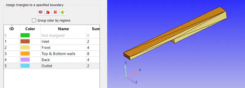
Case Setup
Simulation type
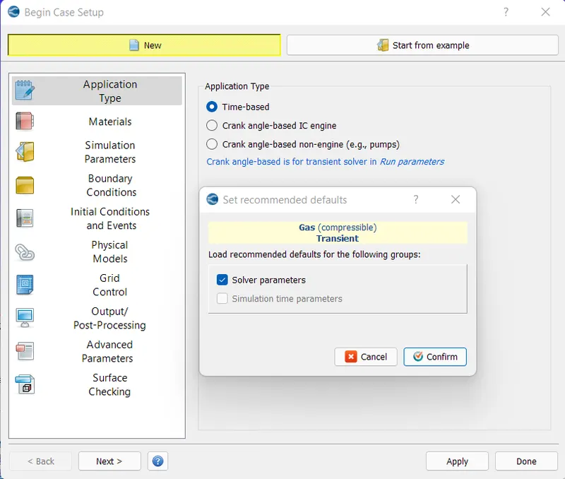
Material
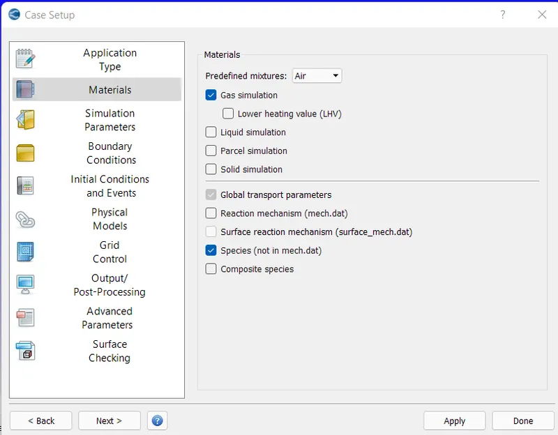
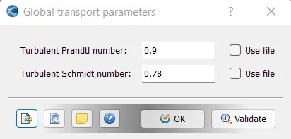
Global Parameters
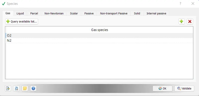
Species
Simulation Parameters
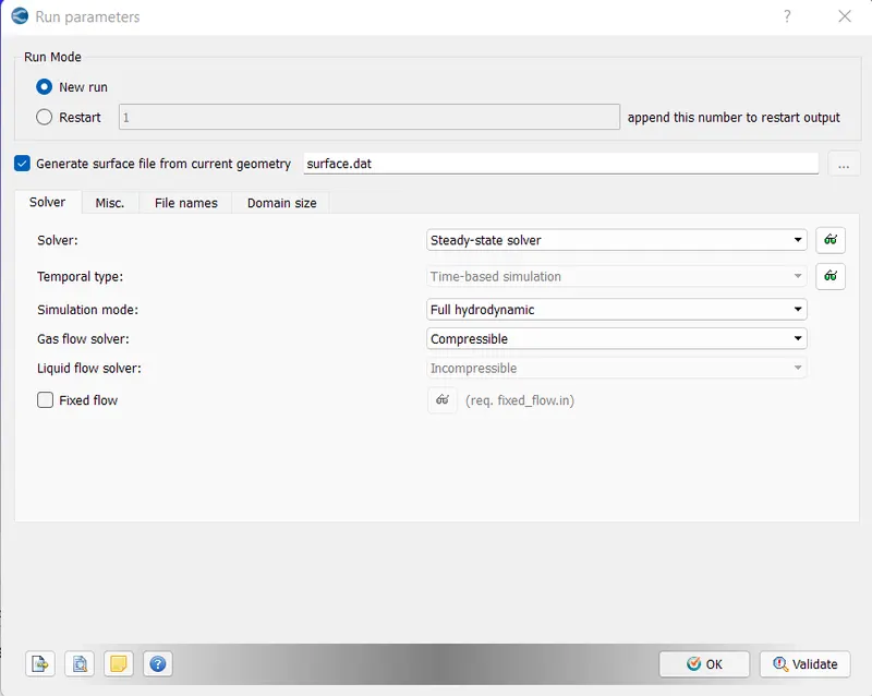
Run Parameters
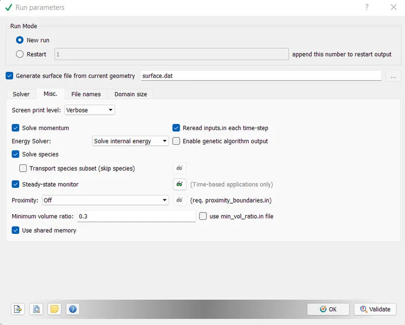
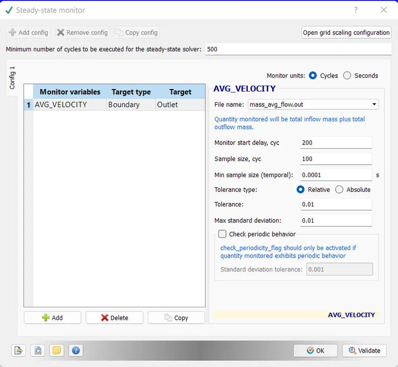
Steady state monitor
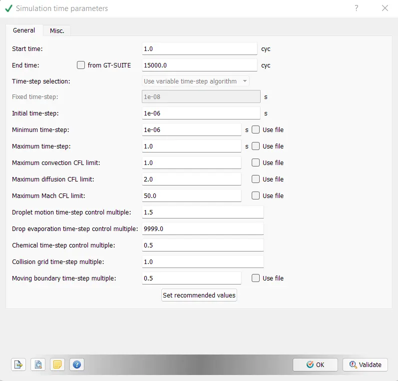
Simulation time parameters
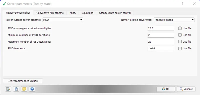
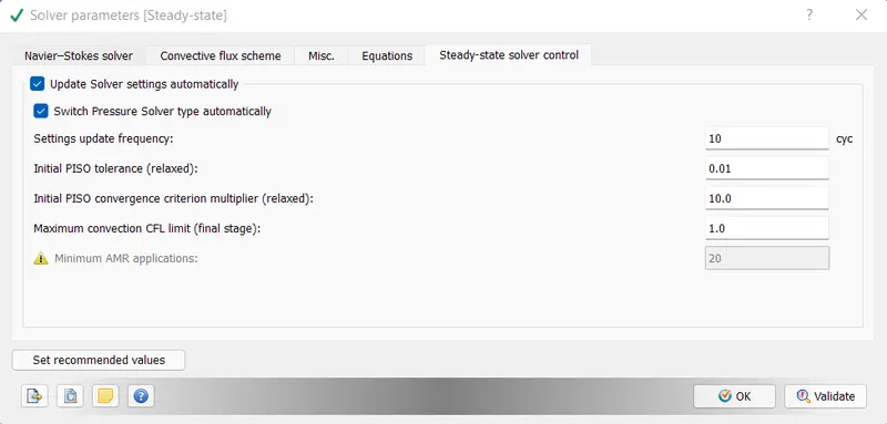
Solver Paameters
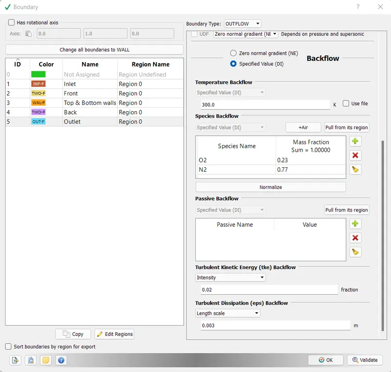
Boundary Conditions
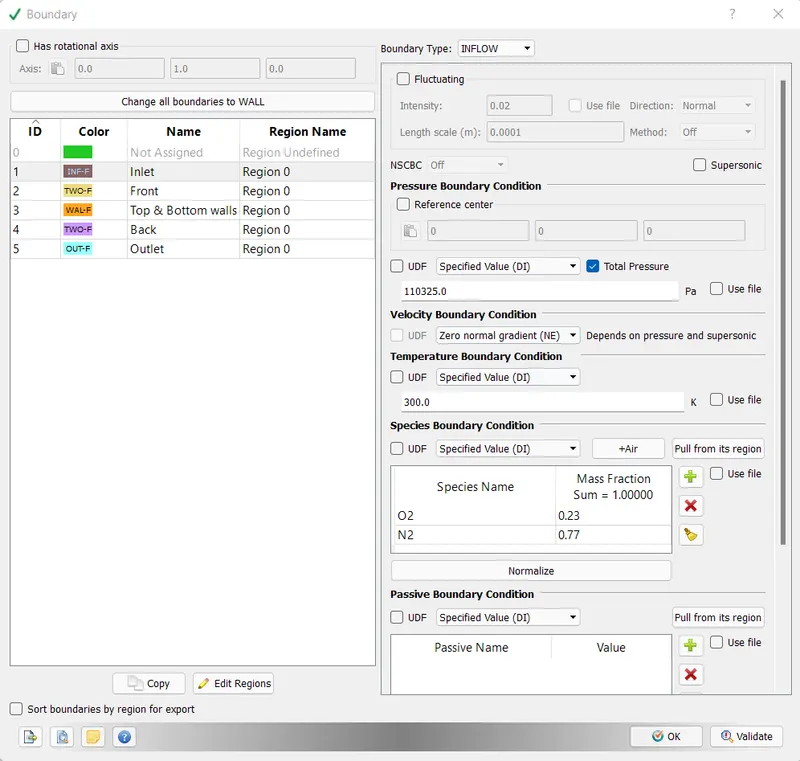
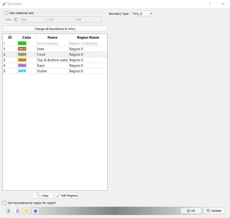
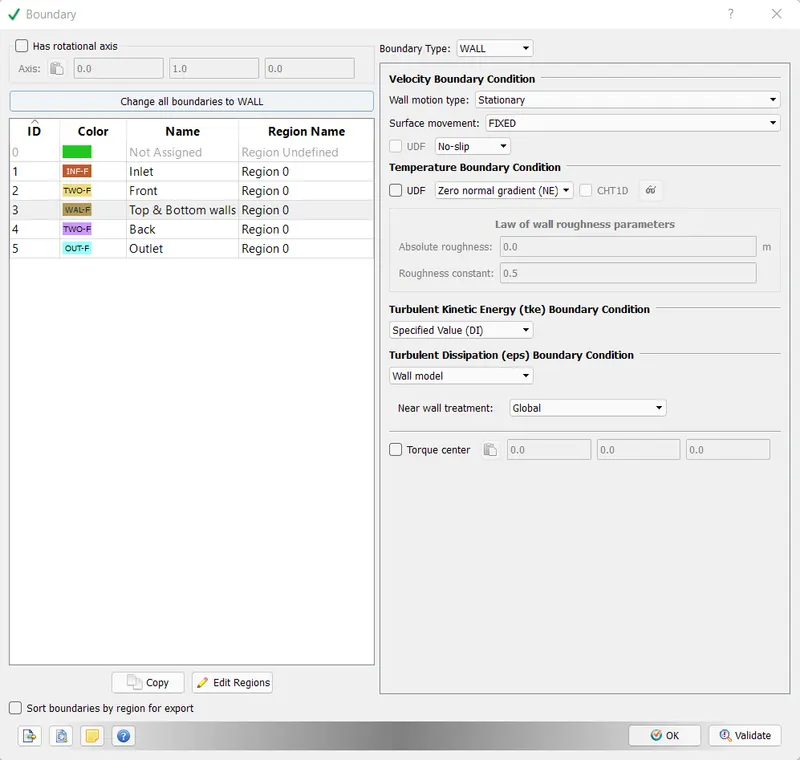
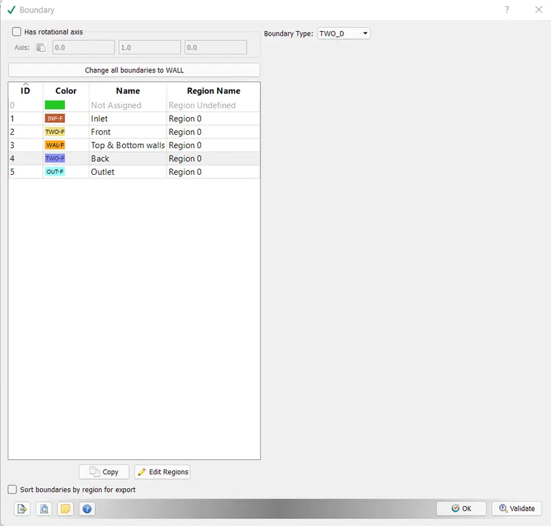
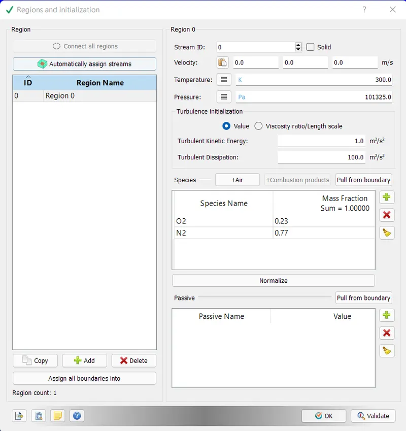
Regions
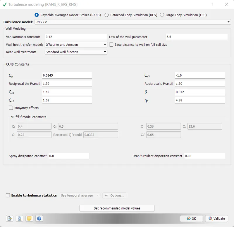
Turbulence Model
Base Grid
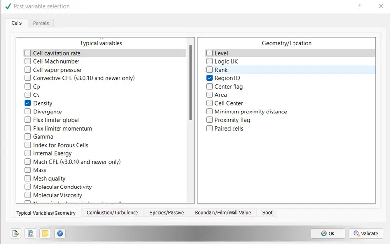
Post Variable Selection
Kept it with default selection
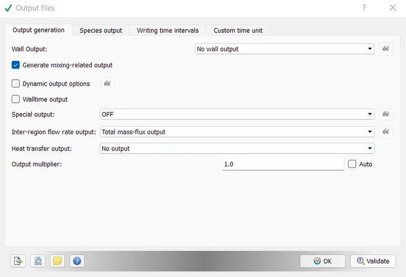
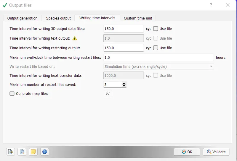
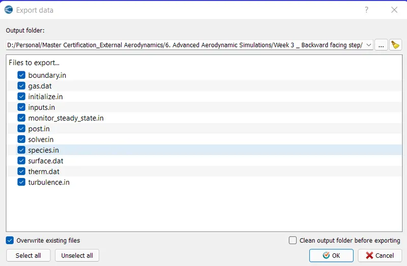
Output Files
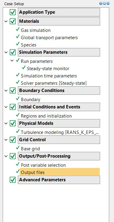
Final Status of Case Setup
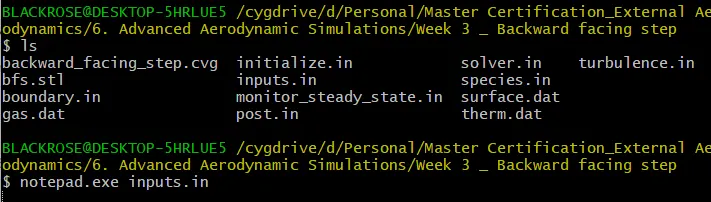
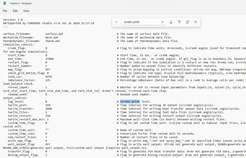
Input Files
Results
Part 1
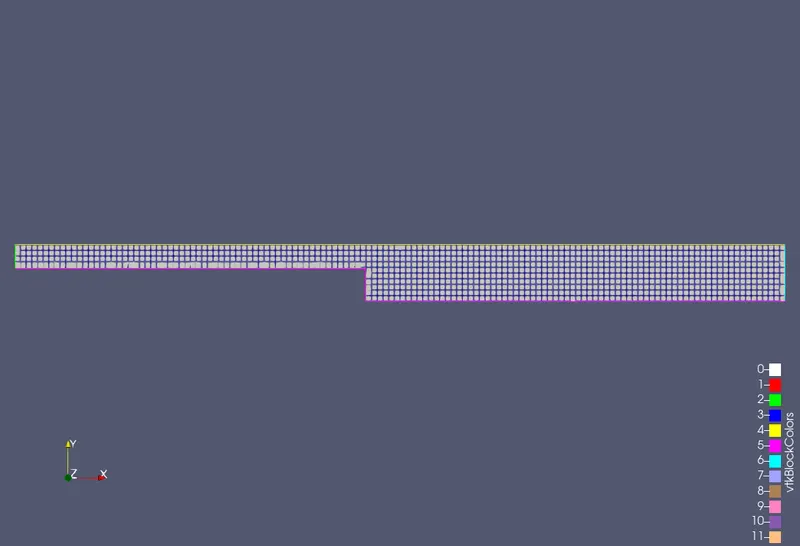
Mesh size = 2e-3m
Mesh
Pressure Contour
Velocity Contour
Plots
Velocity
Pressure
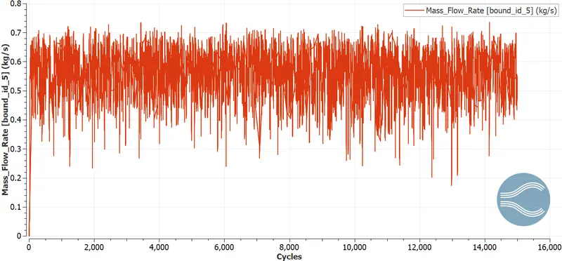
Mass flow rate
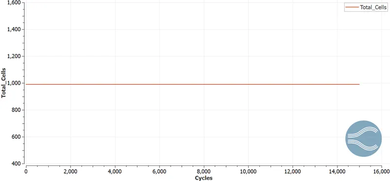
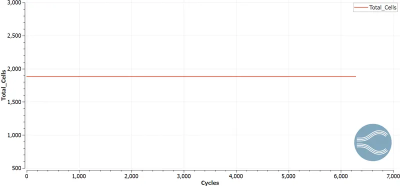
Total cell count
Part 2
Mesh size = 1.5e-3m
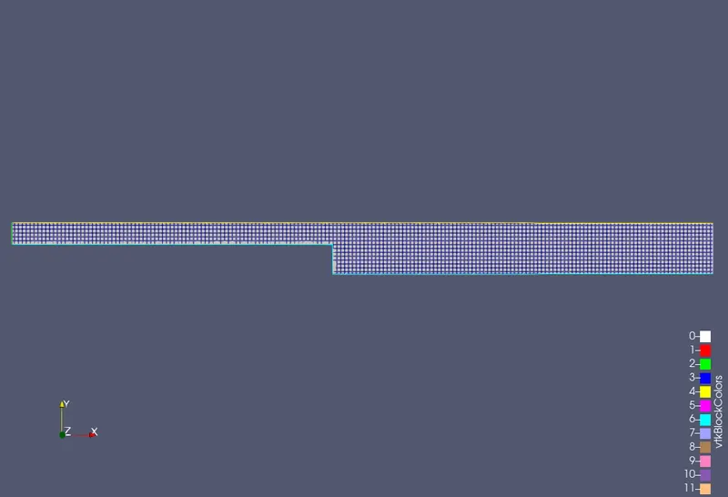
Mesh
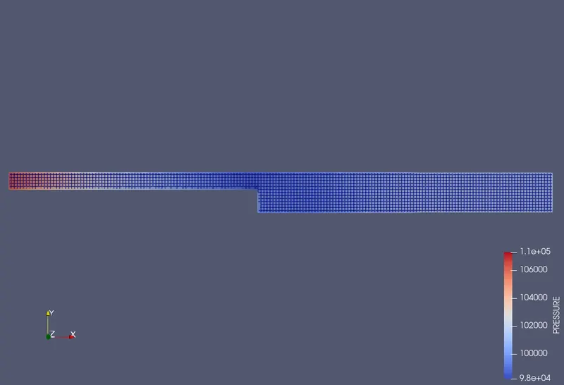
Pressure Contour
Velocity Contour
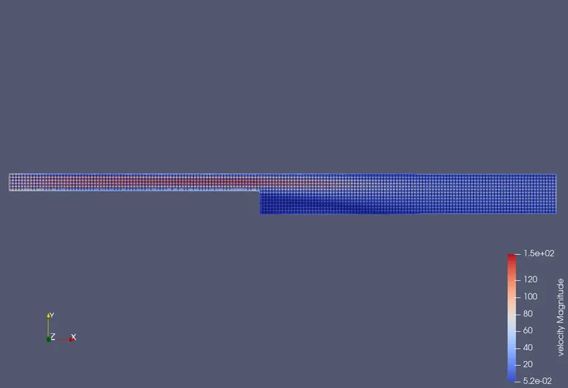
Plots
Velocity
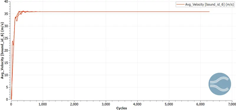
Pressure
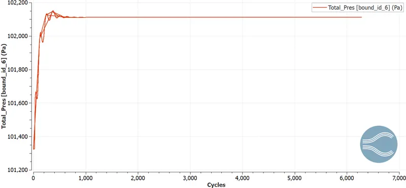
Mass flow rate
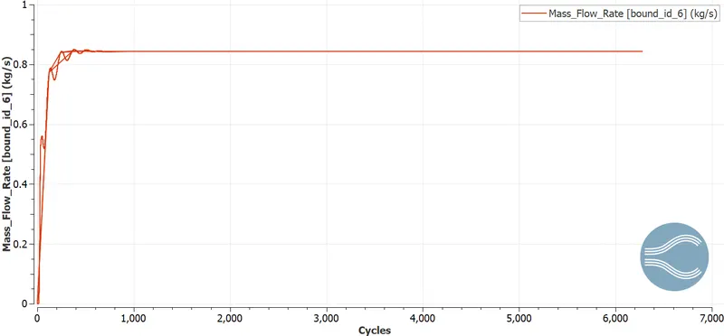
Total cell count
Part 3
Mesh size = 1e-3m
Time taken =
Mesh
Pressure Contour
Velocity Contour
Plots
Velocity
Pressure
Mass flow rate
Total cell count
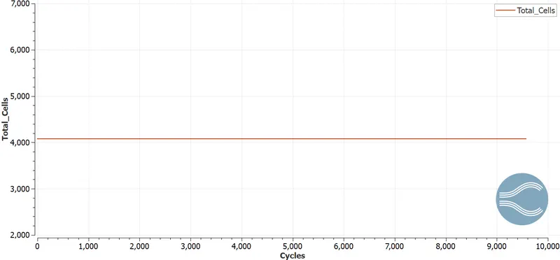
The results with the 1e-3 mm mesh size has the better results because of smaller element size. The flow seperation region is appear in much better way compare to larger sizes used in previous two reults.