Week 3: Flow over a backward facing step
Objective: -
- To simulate the Backward facing step flow for three different mesh grid sizes by using convergent science
- To plot varous plots and contours like Velocity, Pressure, Mass Flow Rate etc.
Backward Step Flow:-
When flow reaches a step it encounters sudden expansion of flow channel which results in a pressure gradient which makes the flow turbulent. This causes flow separation. Although after some distance to retracts to the ussual flow covering the entire area.
Procedure:-
- Geometrybwas created using command CREATE and giving particular coordinates and dimensions to the vertices and joining them to form a 2D shape.
- Using COPY command a copy of the previous shape is made and both of them are joined to form a 3D shape using command loft.
- Enabling Normal vector and using TRANSFORM command all the normal vectors were aligned to same direction.
- Using STEADY STATE simulation Air was introduced as the material which consist of 23% O2 and 77% N2.
- Global Transport Properties were set as the default value
- Run Parameter were set as Full Hydrodynamic with Steady state simulation model and steady state monitor were added which can monitor the progress and can terminate the simulation if it converges after 5000 cycles out of 15000 cycles.
- The solver was set as Pressure based and making rest of the things as default.
- The mest size were taken are 2e-3, 1.5e-3, 1e-3.
- With temperature as 300K and inlet pressure as 110325 Pa and outlet as 101325 Pa the regions were defined
- All the boundaries were defined as respective slow type with Front and Back as 2D wall.
- Top and Bottom were assigned as Law of Wall Boundary with 300K temperature.
- The Turbulence model is defined as RNG K-e putting remaining values as it is.
- A parmanent embded layer was added to fine tune the boundaries mesh with Scale as 1 and layer also as 1.
- Output variables were set as the default selectiona nd write interval was choosen as 100 cyclesto get a better pot processing results
- The Program was executed using CYGWIN command line with 4 parallel processing to get faster result and post processing was done using Converge Science software itself.
Model:-
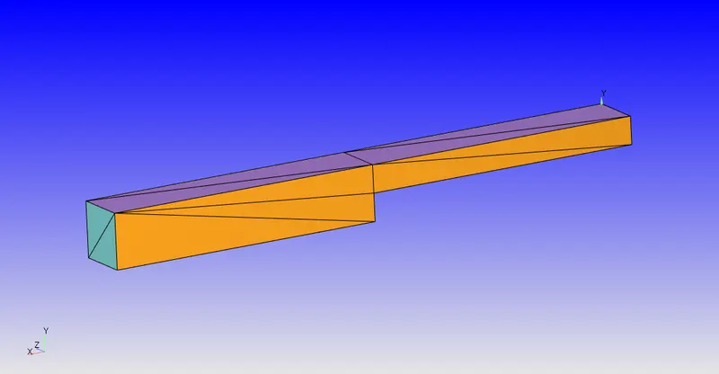
Results:-
Case I :
Mesh Profile
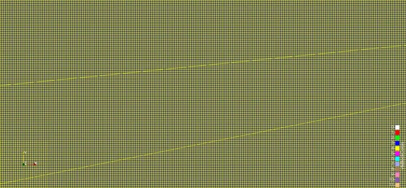
Total Cell Count
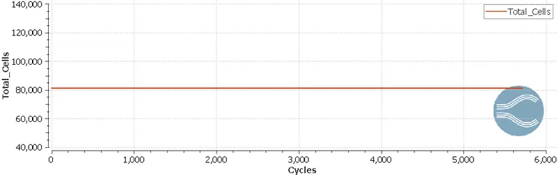
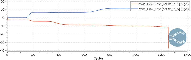
Mass Flow Rate
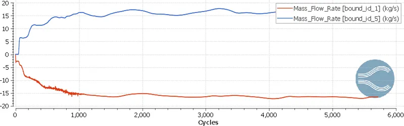
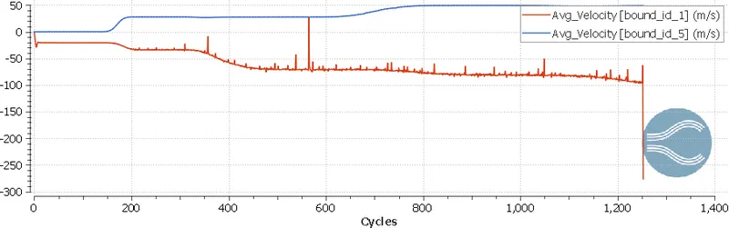
Velocity
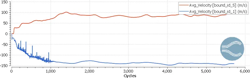
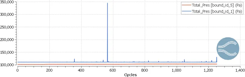
Pressure
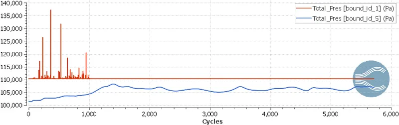
Case II :
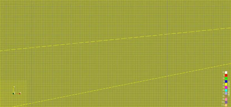
Mesh Profile
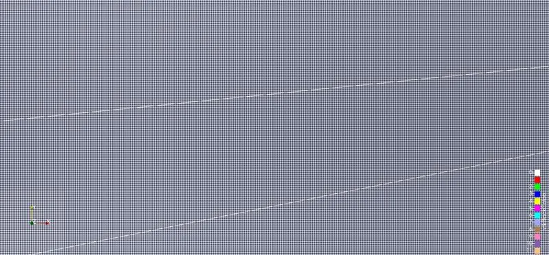
Total Cell Count
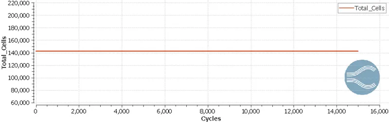
Mass Flow Rate
Velocity
Pressure
Case III :
Mesh Profiile
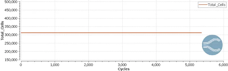
Total Cell Count
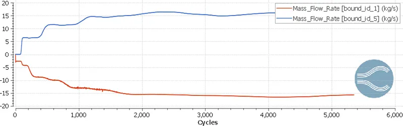
Mass Flow Rate
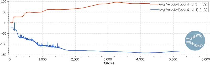
Velocity
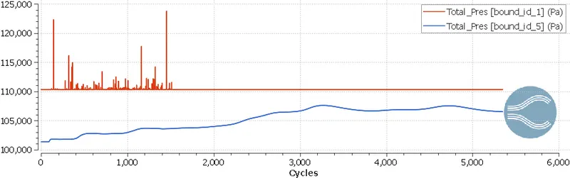
Pressure
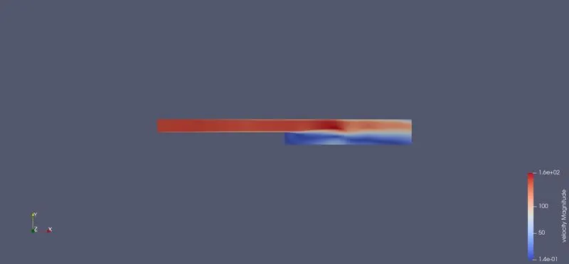
Velocity Contour
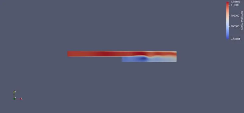
Pressure Contour
Conclusion:-
- Finer the grid more the time it is taking for simulation.
- A suddent change in flow to tubulent can be observed with change in cross section
- The flow taking entire volume later can be observed in the flow
- Lower the grid size finer the simulation is.
- Two layer getting separated at initial phase can be seen.