Week 3: Flow over a backward facing step
Aim: To understand the flow physics involved in classic case of "Backward Facing Step".
Take away:
After reading this article, one will be able to,
- Know what is Backward Facing Step and flow physics involved.
- Export the geometry.
- Setup boundaries.
- Setup the case to replicate the required flow phenomena.
- Post-process the results.
==============================================================================
Theory:
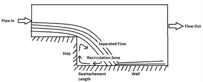
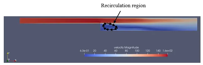
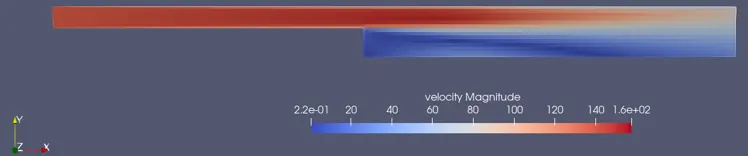
- Fully developed flow enters the domain from left. When the flow reaches the step, because of expansion of flow channel, pressure gradient exists, it detaches and a recirculation zone is formed.
- A turbulent boundary layer encounters a sudden back step, causing flow separation. Later the flow eventually reattaches to the bottom wall.
- Backward-Facing Step (BFS) flow is one representative separation-flow model, which is of significance in both theoretical and engineering development.
- Various applications for BFS flow can be found in our daily life, such as the airfoils at large attack angle, the spoiler flows, separation flow behind a vehicle, inlet tunnel flow of engine or inside a condenser/combustor, and also the flow around a boat or a building.
- It is a basic model that involves the most important features of a separated flow: free shear flow separation, vortex evolution and re-attachment.
- Flow separation is one classic topic in fluid dynamics, which has become one key topic in external flows and is closely related to aerodynamic design of vehicles, mechanics and other moving bodies.
- The free shear layer evolutions are the dominant factor for separation process.
- Separation flow in external and internal flows show different behaviors due to the confinement of walls and the specific design of model geometry.
- As a typical kind of separation flow model, Backward-Facing Step (BFS) has been studied as an important flow dynamic model for more than half a century, while the real step flow situations/designs can be found with the early years of natural world.
- Backward facing step is widely used as code validation with experimental study.
Reference:
1. Link
2. Link
============================================================================
Importing Geometry:
- File should be in .STL format.
- One way to do is, simlpy drag and drop the file in the graphics window in CONVERGE STUDIO.
- Second way to do is by selecting "import" option and then "import STL".
Geometry:
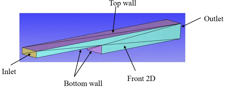
Assigning Boundary:
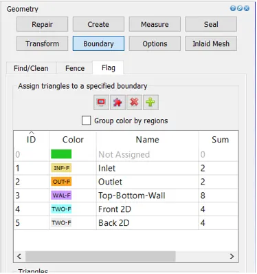
- Navigate to geometry dock and select "Boundary"
- Assign respective boundary according to the problem statement.
Setting up the case:
- Select "Begin Case Setup".
- Select Time based.
- Select "Materials" in the same window.
- Select Air. Uncheck reaction and check species.
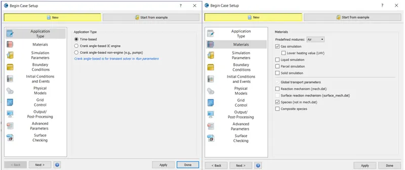
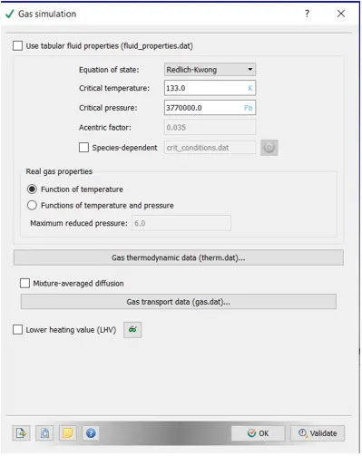
- Select "Gas Simulation"
- Set default values.
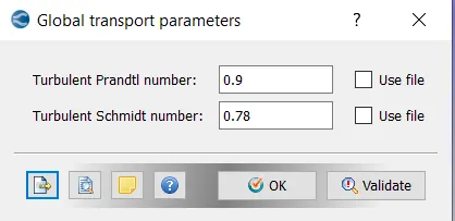
- Select "Global transport parameters".
- Set default values.
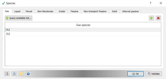
- Select "Species".
- Add O2 and N2.
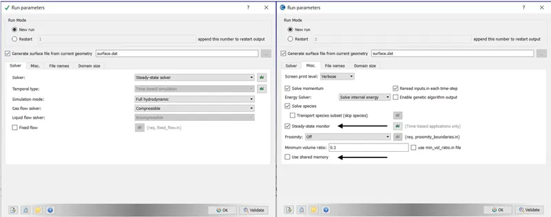
- Select "Run parameters".
- select Steady-state solver.
- Navigate to "Misc.". Select "Steady-state monitor" and deselect "Use shared memory".
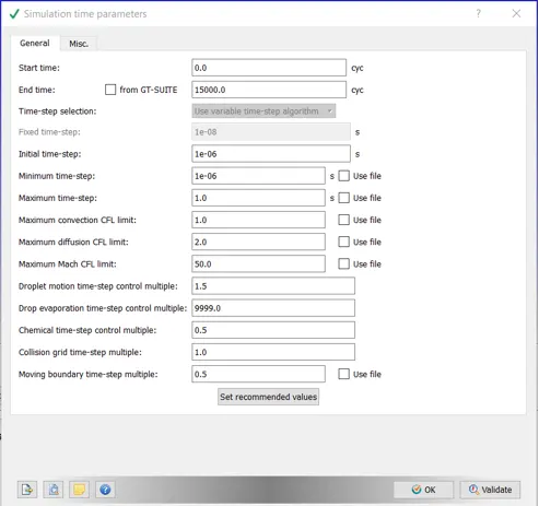
- Select "Simulation time parameters".
- End time: 15000 cycles
- Initial time step: 1e-06 s
- Minimum time-step: 1e-06 s
- Maximum time-step: 1 s
- Maximum convection CFL limit: 1
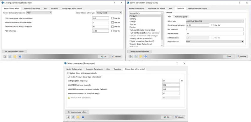
- Select "Solver parametrs".
- Make sure it is "density based" under "Navier-Stokes solver type".
- Navigate to "Equations" tab in the same window. Select pressure and select "none" for "preconditioner".
- Navigate to "Steady-state solver control". Assign a value of 0.5 for "Maximum convection CFL limi (final stage)".
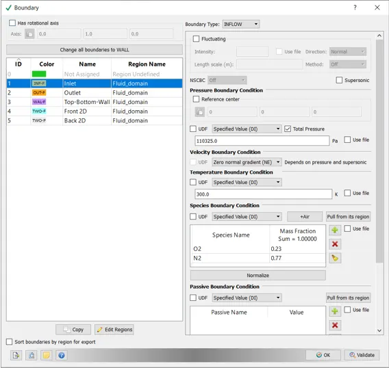
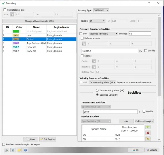
- Select "Boundary" under "Boundary conditions" tab.
- Assign boundary conditions.
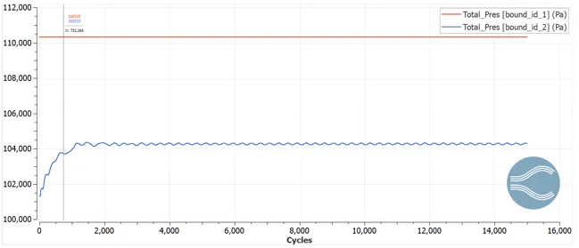
- Inlet: Total pressure of 110325 Pa.
- Outlet: Total Pressure of 101325.0 Pa.
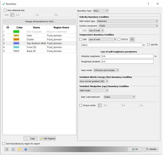
- Top-Bottom-Wall: Assign wall boundary condition as shown in fig. below.
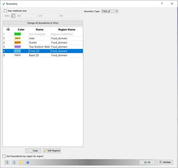
- Front and back as 2D.
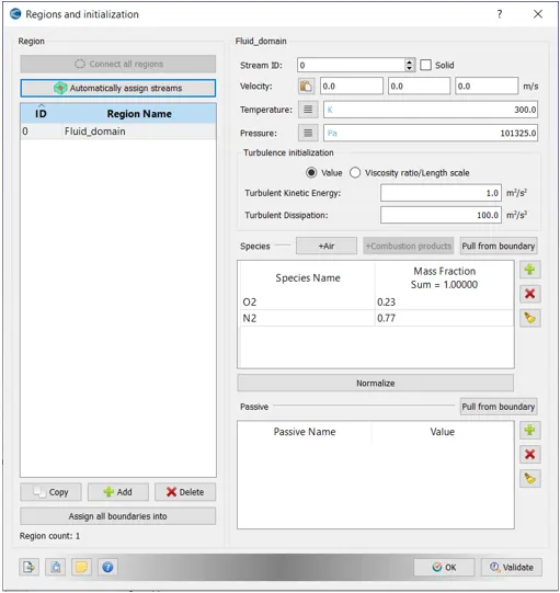
- Select "Regions and initialization".
- Create a region by clicking on the "+" icon and name it to fluid domain or what ever you like.
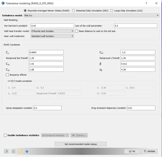
- Select "Turbulence Modelling".
- Select default.
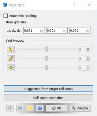
- Select "Base Grid".
- Enter size mentioned below:

- Select the "Post variable selection". Choose appropriate variables to be plotted.
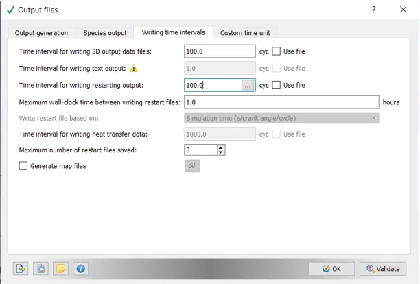
- Select "Output files". Select the following as shown in the figure.
- The final step is to export all the necessary files into a folder created.
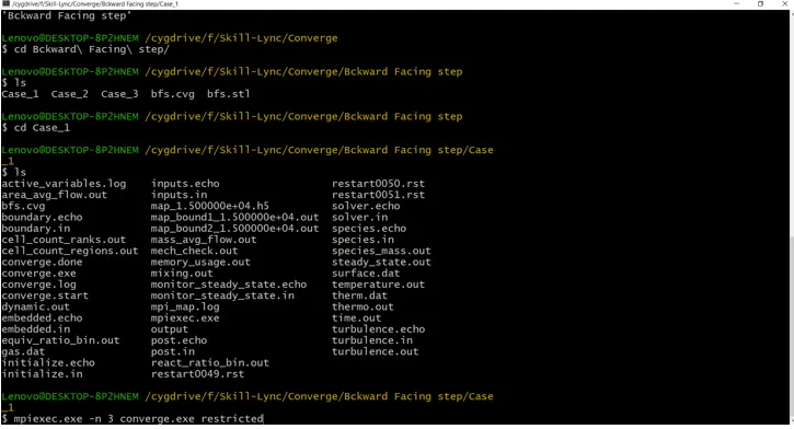
- Launch Cygwin and navigate to the folder where all the input files are located.
- Enter the command: "mpiexec.exe -n 3 converge.exe restricted".
- The above command will start running the simulation.
==============================================================================
Results:
Case 1: Mesh size = 0.002, 0.002, 0.002 (meters (x,y,z))
Results from CONVERGE:
- Mesh:

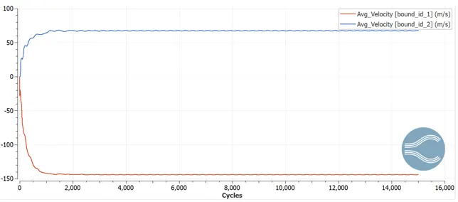
- Velocity Plot:
- Total Pressure Plot:
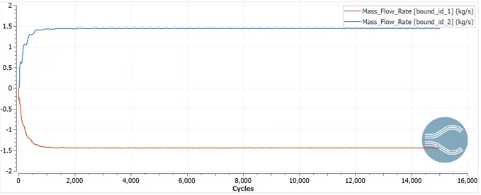
- Mass Flow Rate Plot:
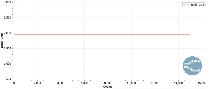
- Mesh Count:
Results from PARAVIEW:
- Velocity Contour:
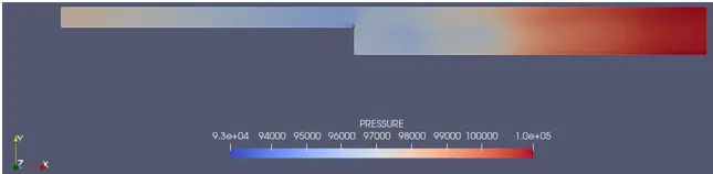
- Pressure Contour:
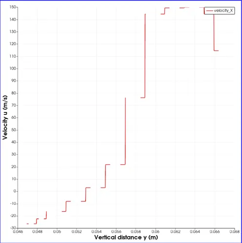
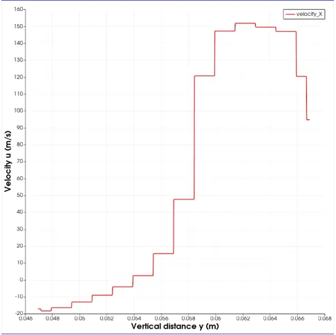
- Velocity Profile at x = 0.14 m
==============================================================================
Case 2: Mesh size = 0.0015, 0.0015, 0.0015 (meters (x,y,z))
Results from CONVERGE:
- Mesh:

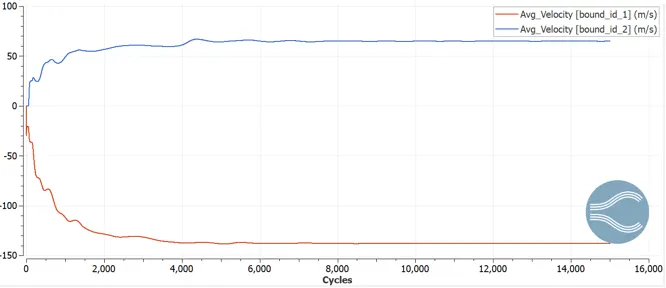
- Velocity Plot:
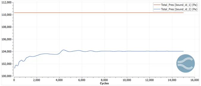
- Total Pressure Plot:
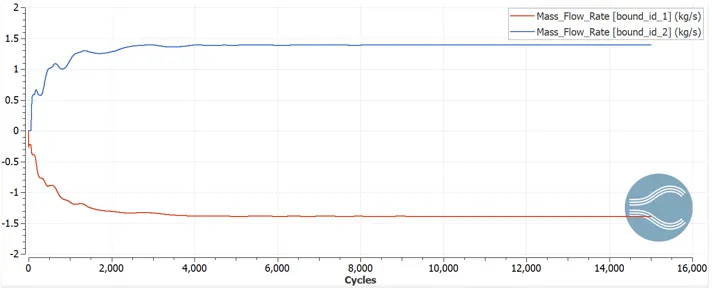
- Mass Flow Rate Plot:
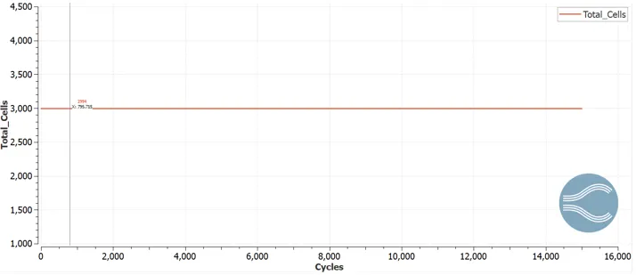
- Mesh Count:
Results from PARAVIEW:
- Velocity Contour:
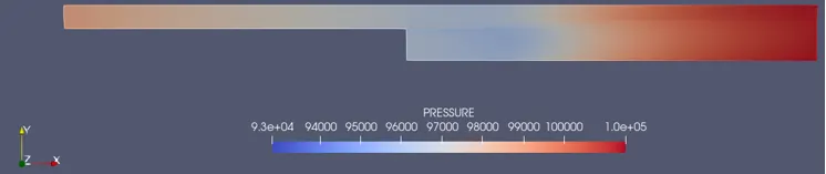
- Pressure Contour:
- Velocity Profile at x = 0.14 m
==============================================================================
Case 3: Mesh size = 0.001, 0.001, 0.001 (meters (x,y,z))
Results from CONVERGE:
- Mesh:

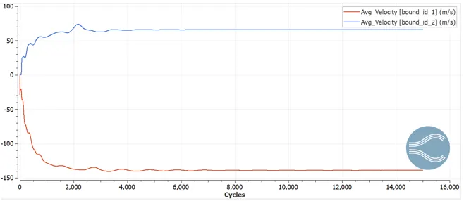
- Velocity Plot:
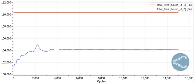
- Total Pressure Plot:
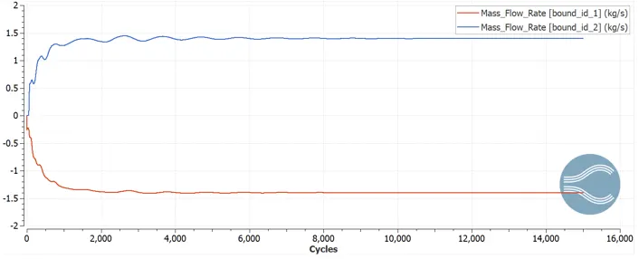
- Mass Flow Rate Plot:
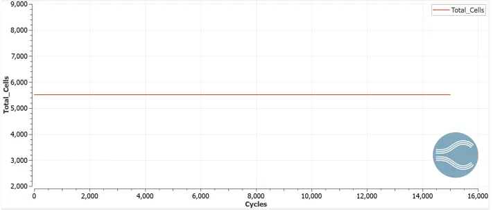
- Mesh Count:
Results from PARAVIEW:
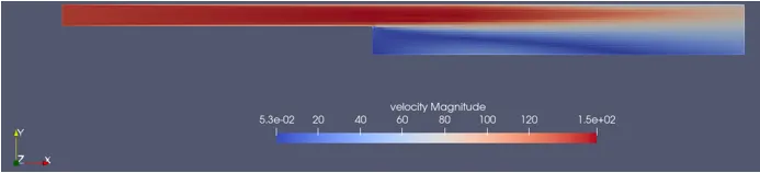
- Velocity Contour:
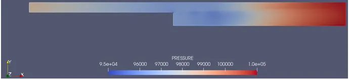
- Pressure Contour:
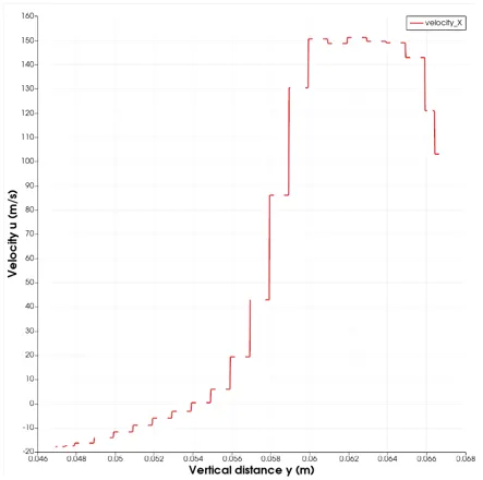
- Velocity Profile at x = 0.14 m
==============================================================================
Reason for flow separation:
- Separation and reattachment of turbulent flows occur in many practical engineering applications.
- It is seen both in internal flow systems such as diffusers, combustors and channels with sudden expansions, and in external flows like flow around airfoil and building.
- In these situations, the flow experiences an adverse pressure gradient, which causes the boundary layer to separate from the solid surface.
- The flow subsequently reattaches downstream forming a recirculation bubble.
- The presence of a separated flow, together with a reattaching flow, gives rise to increased unsteadiness, pressure fluctuations which may lead to structure vibrations and noise.
Adverse Pressure Gradient:
- In fluid dynamics, an adverse pressure gradient is a pressure gradient in which the static pressure increases in the direction of the flow. Mathematically this is expressed as dP/dx > 0 for a flow in the positive x-direction.
- This is important for boundary layers.
- Increasing the fluid pressure is akin to increasing the potential energy of the fluid, leading to a reduced kinetic energy and a deceleration of the fluid.
- Since the fluid in the inner part of the boundary layer is slower, it is more greatly affected by the increasing pressure gradient.
- For a large enough pressure increase, this fluid may slow to zero velocity or even become reversed causing a flow separation.
- This has very significant consequences in aerodynamics since flow separation significantly modifies the pressure distribution along the surface and hence the lift and drag characteristics.
Conclusion:
- Mesh independent study was done.
- Looking at the line plots ploted in CONVERGE, for the first case the solution has still not stabalized and has some wiggles after 15,000 iterations.
- Considering case two and three it seems the solutions has pretty much converged at 15,000 iterations.
- A more finer mesh can be drawn for better results.
- Flow separates after the step as there is suddenchange in geometry which increase the static pressure therefore causing reversal in flow.