Week 3: Flow over a backward facing step
AIM:
To run the Backward facing step case for three different base mesh sizes of dx=dy=dz=2e-3,1.5e-3 and 1e-3m and to post process results for the following
1. The mesh (i.e surface with edges) for all the 3 base mesh sizes
2. Pressure and velocity contours
3. Plots of velocity, pressure, mass flow rate and total cell count for all the 3 base mesh sizes
4. Explaination for where and why separation is taking place.
DESCRIPTION:
A Backward facing step is widely used for its application of turbulence in internal flows.The flow separation is caused due to the sudden changes in the geometry and the inlet and outlet differences. The flow separation causes a point of reattachment and a point of recirculation.
The backward facing step represents separation flows, which can be widely seen in aerodynamic flows, heat transfer, engine flows, condensers, vehicles and flow around the building.
STEPS FOR SIMULATION OF BACKWARD STEP FACING
Loading the Geometry model in Converge studio
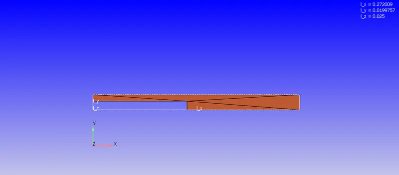
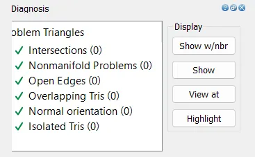
Running the diagnosis we see no errors
Or to create the geometry using the below following steps
Create>vertex at origin a point
Then for inlet another point at 0.01m in Y
length of edge in y-direction at inlet 1.2383726239204E-01
Total length of edge in y-direction: 2.7200946211815E-01
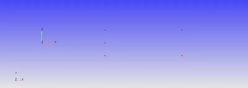
The using three vertices creating triangles
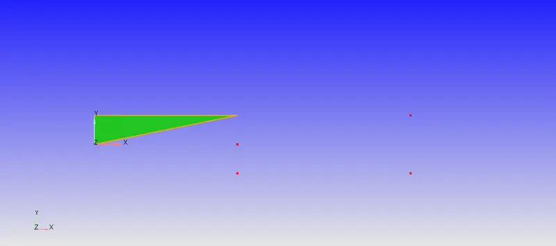
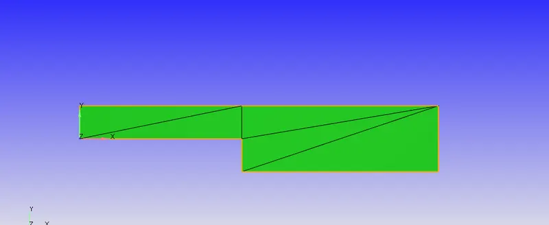
Then using offset create>copy>triangles at -0.025m in -ve Z-direction
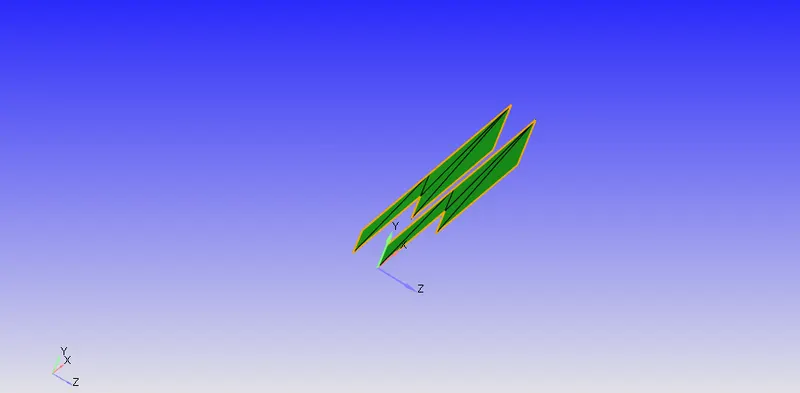
Then using loft edges
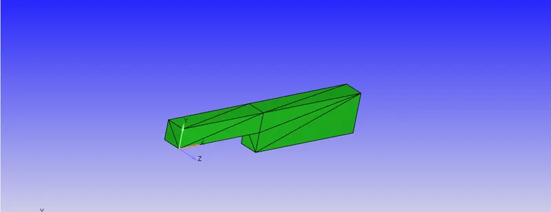
Now checking the normals
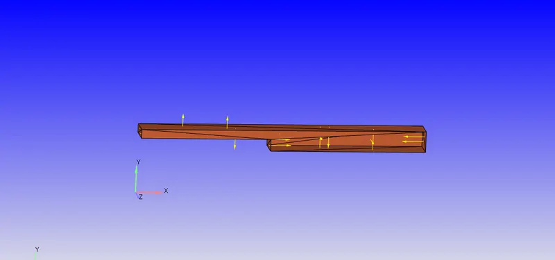
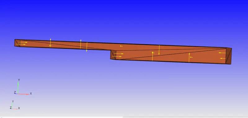
we see that the some normals are points outwards and some are pointing inwards.But we need all normals to point inwards as we are simulating the flow with inside for geometry.
so changing the normals by using the 'Transform tool' as follow
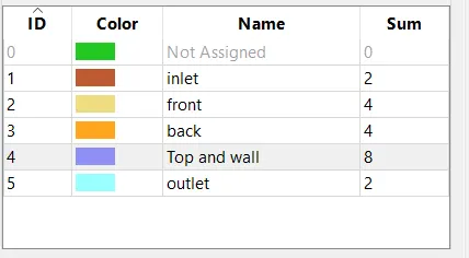
BOUNDARY FLAGGING:
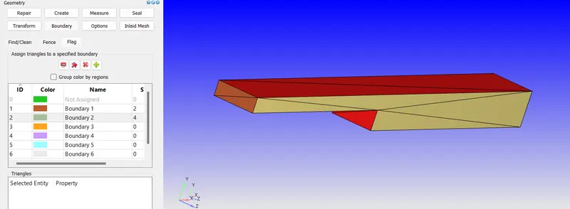
By using the traingle>angle selection we select the inlet
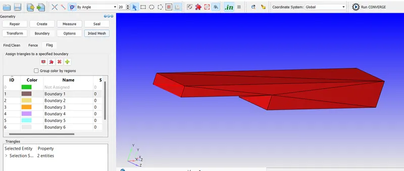
Boundaary 2 side face
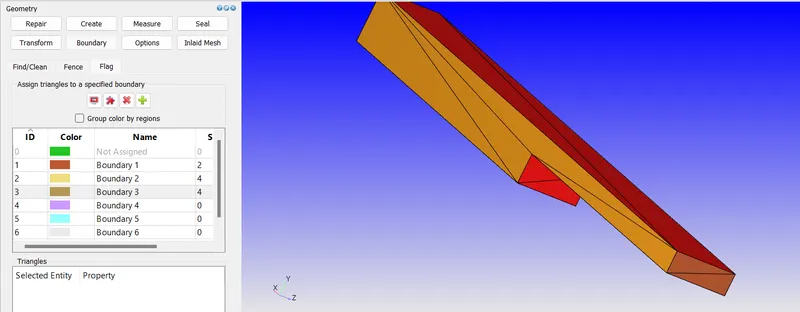
Boundary 3 side face
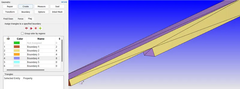
Boundary 4 top & bottom
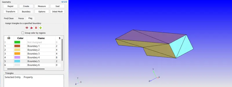
Boundary 5 outlet
CASE SETUP
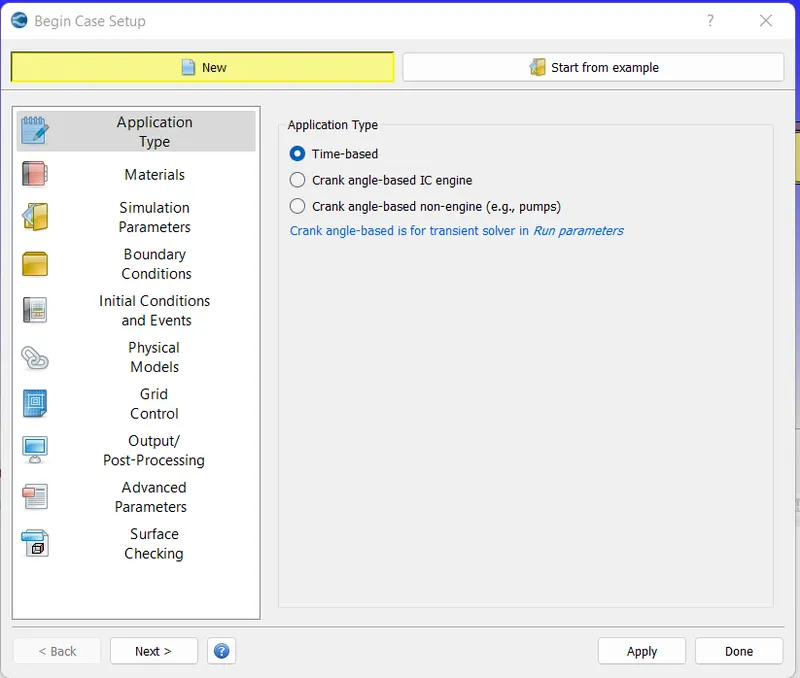
Choosing time based simulation
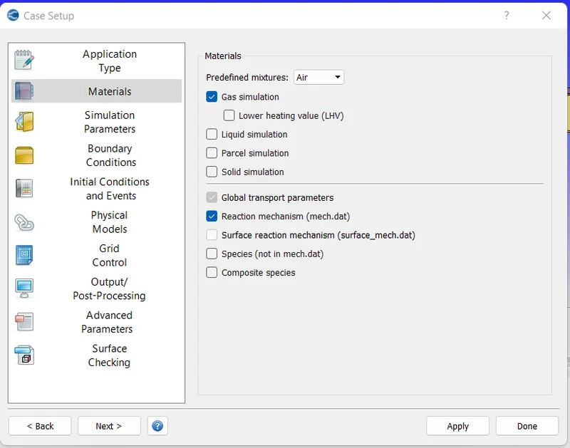
Choosing materials as Air
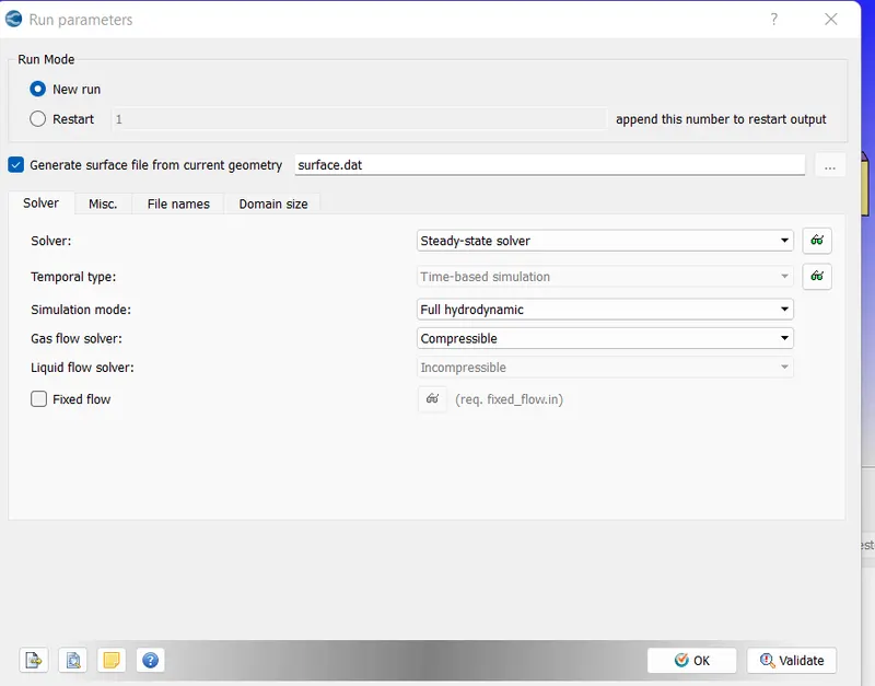
Run parameters choosing as steady state with full hydrodynamic mode as the model is not complex like IC engines
For simulation time parameters we run for 15000 cycles with minimum time 1e-6
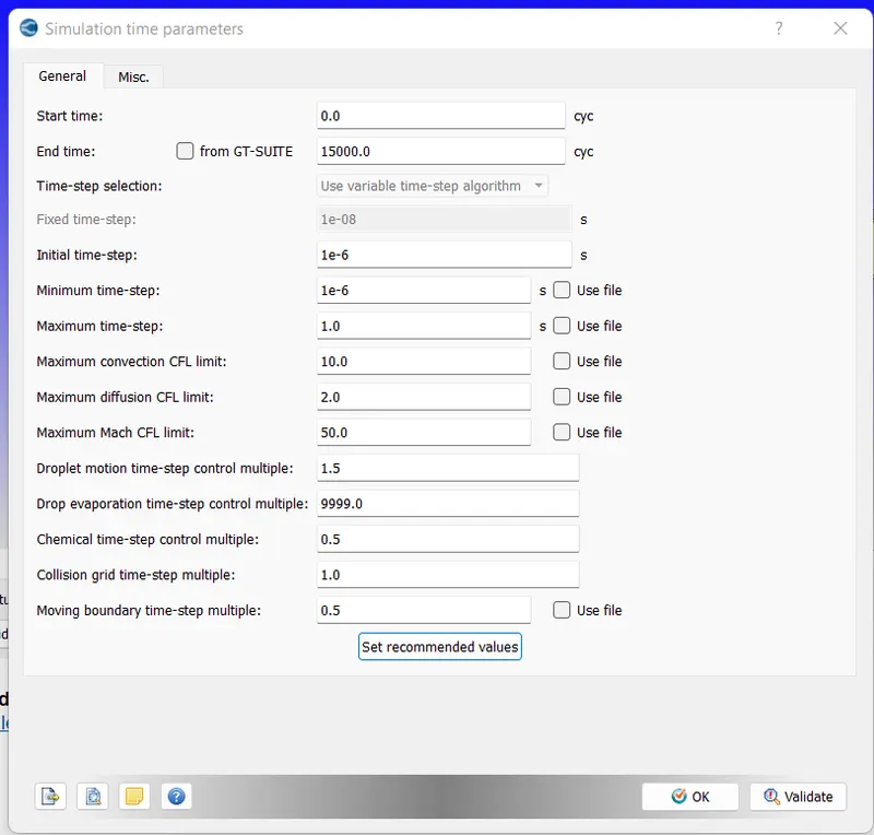
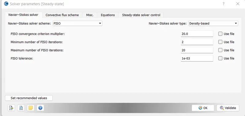
We use density based solver for parameters
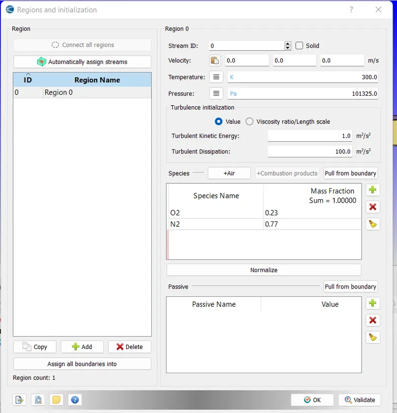
Next for Regions, we create region filles with air with temperature defult 300K and pressure default 1atm
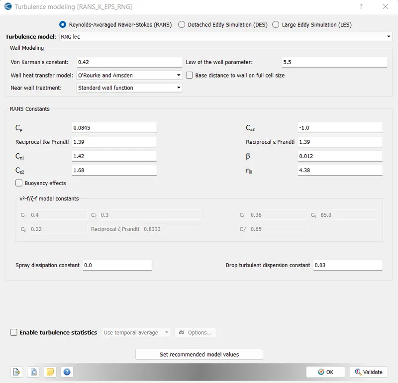
Using turbulence RNG k-epsilon
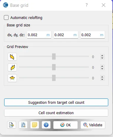
Grid size is 2e-3
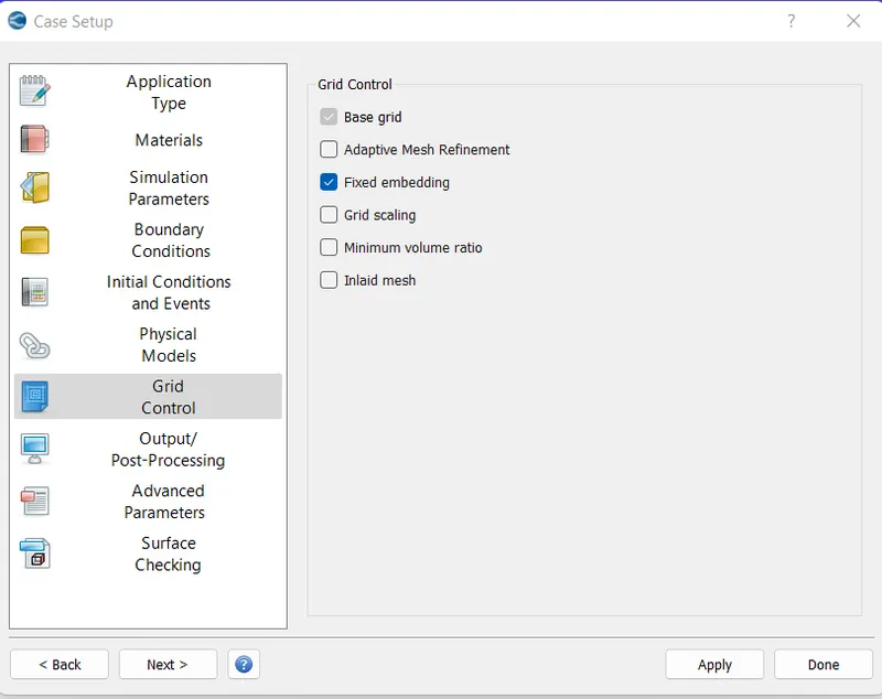
enablng the fixed embedding
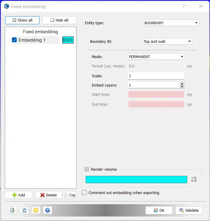
with boundary embedding for top and wall with scale 1 (means cell size of 1mm at top and wall boundary) and with permanent mode
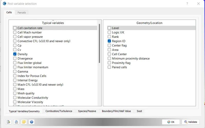
For post processing keeping default
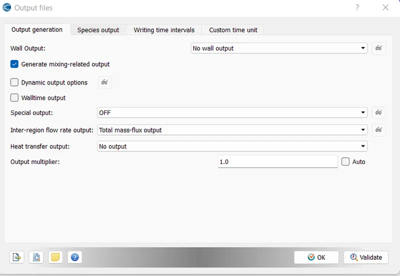
Output files as default
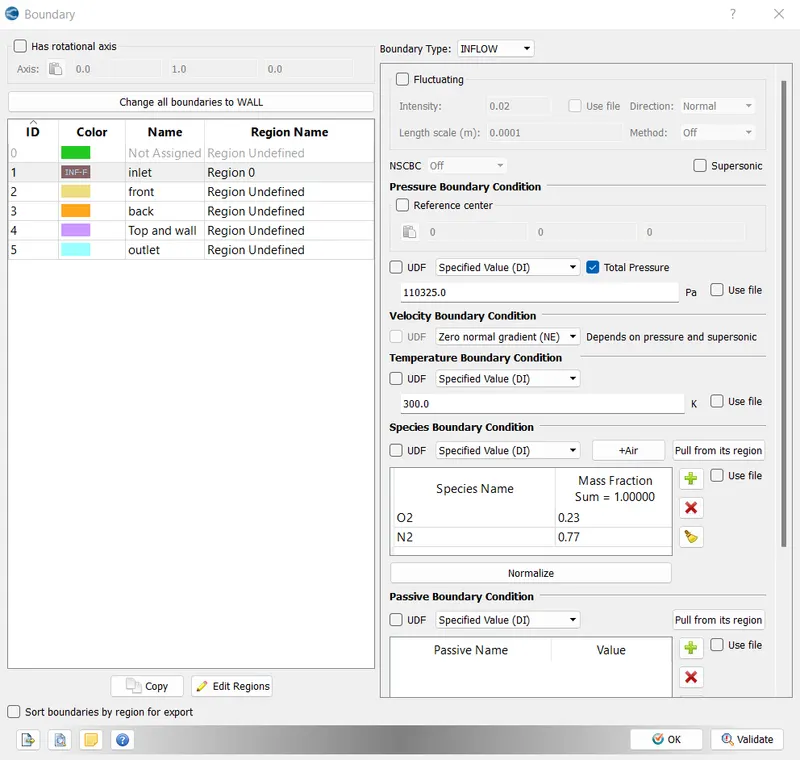
For boundary
For inlet with inflow type and 110325Pa pressure with temperature default and with Air as species with region selection
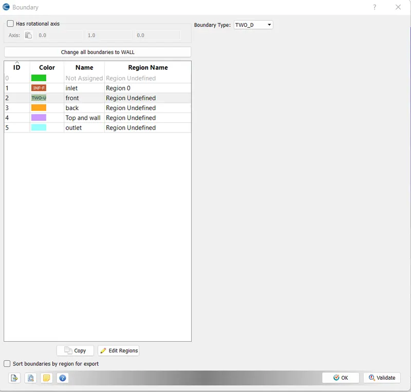
As we need 2D simulation we assign front and back i.e in z-direction as Two-D wall as below
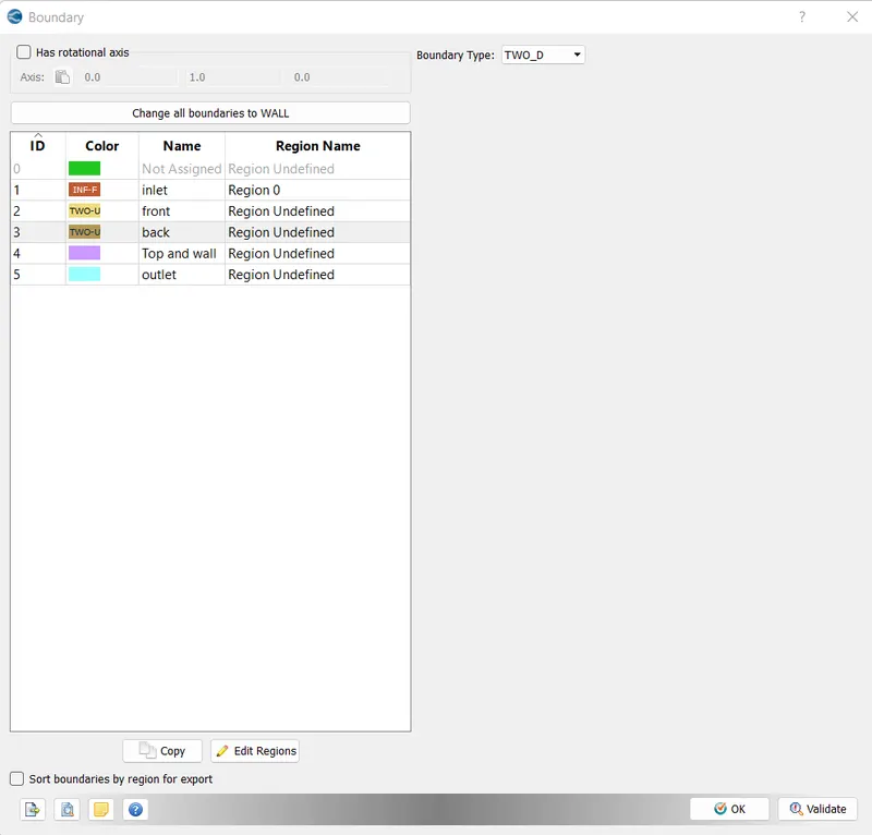
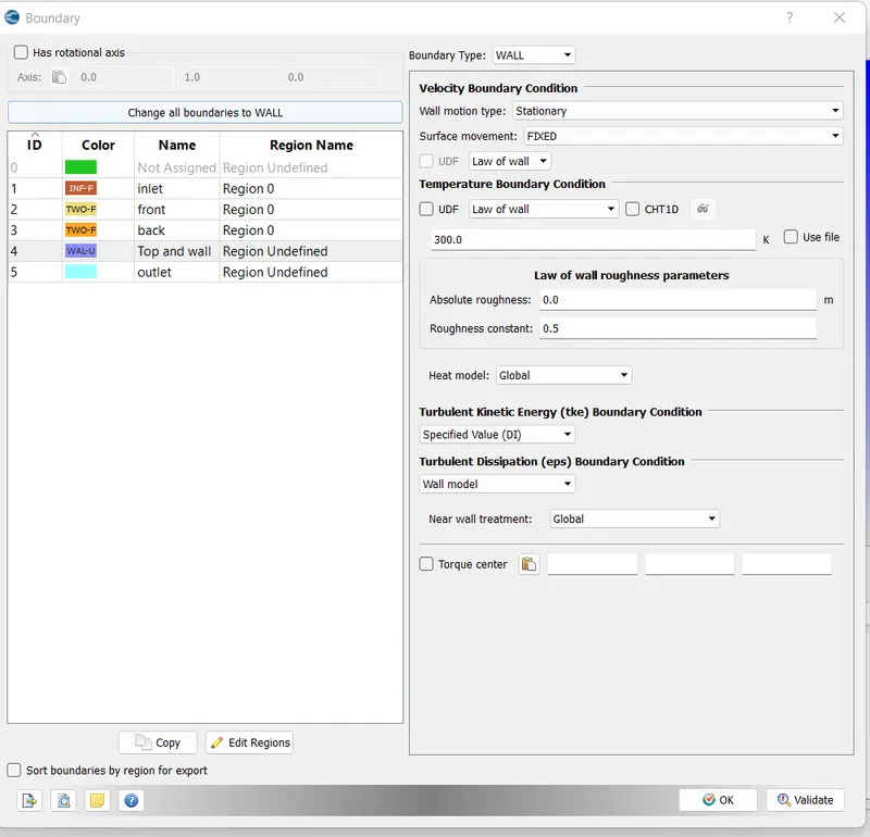
For top and wall as law of wall
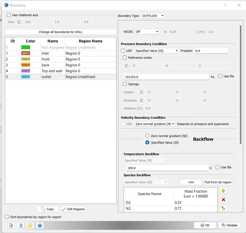
For outlet with outflow type and 1atm with air as backflow
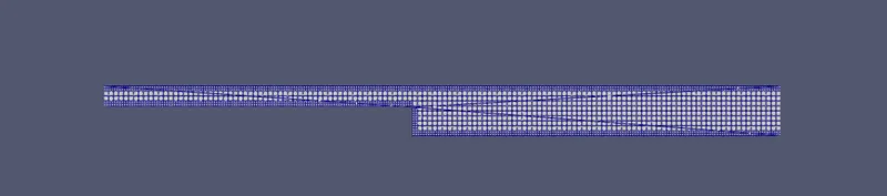
CASE-1: MESH SIZE OF 2e-3
The Mesh looks as follows
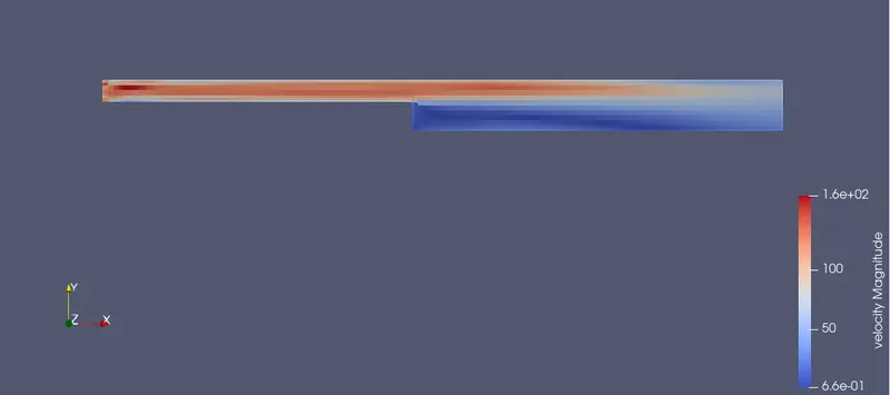
The velocity contour is
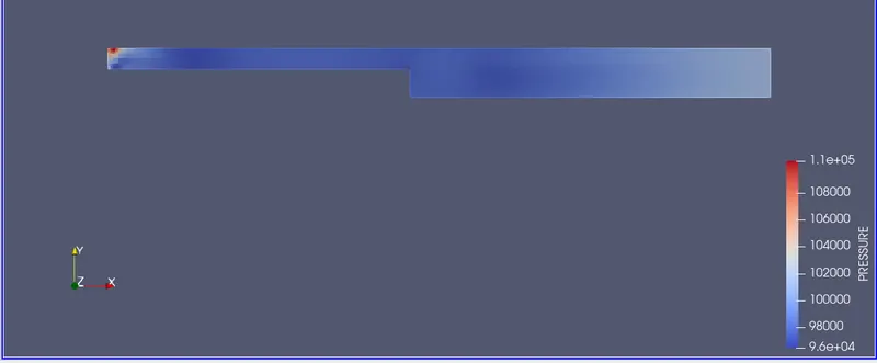
The pressure contour is
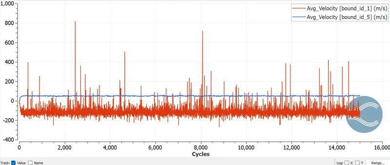
The velocity plot is
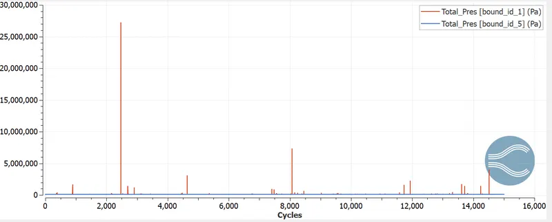
The pressure plot is
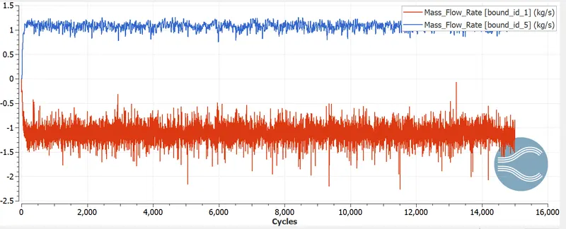
The Mass flow plot is
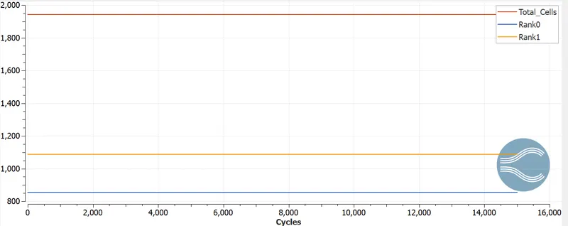
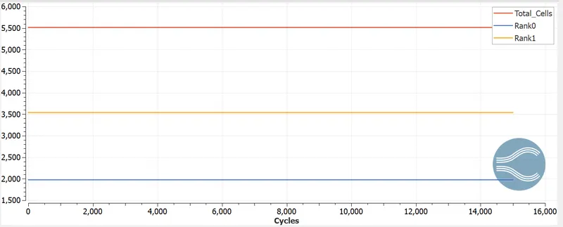
Total cell count plot is
Animation
CASE-2: MESH SIZE OF 1.5e-3
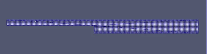
The Mesh looks as follows
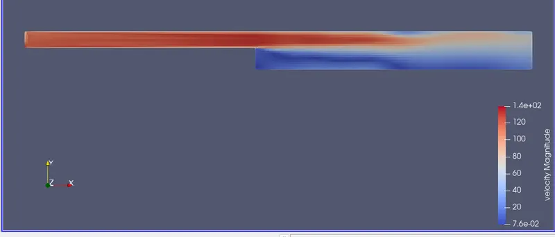
The velocity contour is
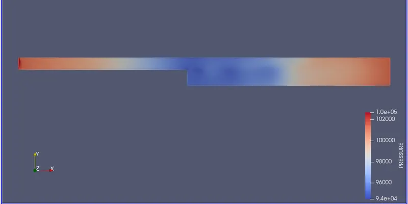
The pressure contour is
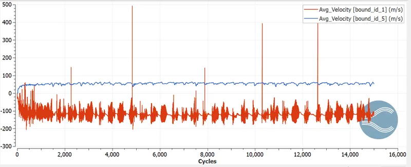
The velocity plot is
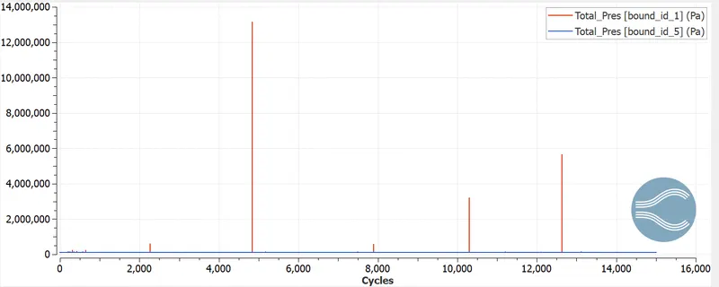
The pressure plot is
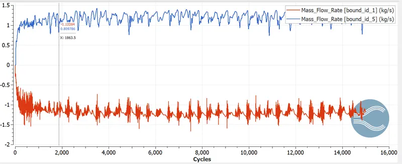
The Mass flow plot is
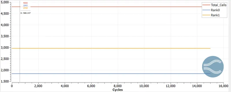
Total cell count plot is
Animation
CASE-3: MESH SIZE OF 1.2e-3
The Mesh looks as follows
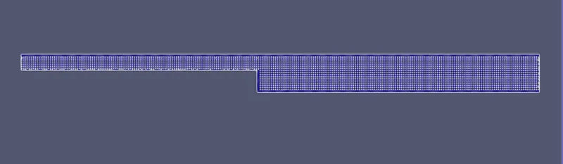
The velocity contour is
The pressure contour is
The velocity plot is
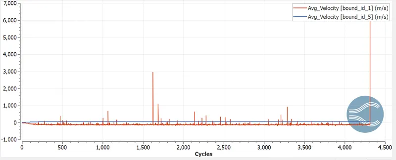
The pressure plot is
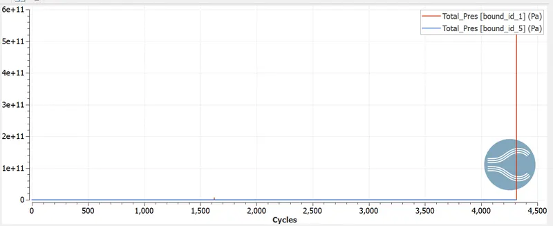
The Mass flow plot is
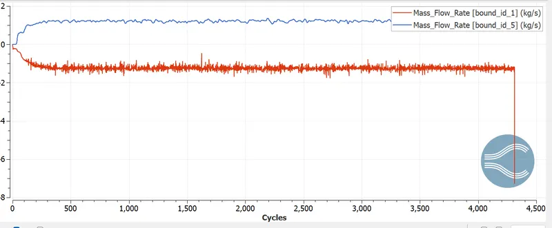
Total cell count plot is
IMPORTANT COMMAND USED IN CYGWIN FOR POST-PROCESSING:
For post processing of oitput results we first go to the directory where the export input files of converge are located/saved and run the 'mpiexec.exe -n 2 converge.exe restricted' code in Cygwin with 2 parallel processor and the simulation starts running and output data is printed.
Then The output data is post-processed using the 'mpiexec.exe post_convert_30_msmpi_64.exe' code and the contours are generated and using Paraview the contours are studies and observed.
The line plots are studied in converge line plotting GUI.
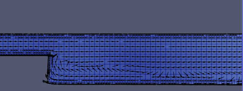
SEPARATION REGION:
For Case-1
For case-2
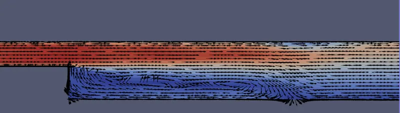
Air enters the inlet of backward step facing due to the sudden changes in the geometry section at 0.12m from the inlet, the air gets separated from the boundary leading to the deacceleration of the flow and reduction in the static pressure in that region and beyond that, as seen in the above recirculation zones being formed and reattachment to the boundary layers occurs.
CONCLUSION:
Backward facing step can help in analysing the physics near the boundary wall.
Flow separation create a wake region at the flow end which causes a recirculation region due to the adverse pressure gradient, creating turbulence and formation of eddies.
With decrease in cell size the number of cells gets increase and vice-versa. with decrease in cell size the simulation time increases.
The refined mesh that is 0.001m shows the velocity clearly in the velocity contour and flow separation can be seen.
The velocity and pressure are decreased in the recirculation region.