Week 3 - External flow simulation over an Ahmed body.
AIM - To simulate the external flow over an Ahmed body and find drag coefficient.
INTRODUCTION -
1.Ahmed body and Importance
The Ahmed body is a generic car body, also a more simplified one. the airflow around Ahmed's body captures essential flow features around an automobile, it was defined the experimental works of Ahmed.
The Ahmed body is used to validate the numerical model in the industry and then it is used to design a new model with the same validated numerical model.
2.Explain the reason for the negative pressure in the wake region.
A negative pressure gradient occurs due to the boundary layer phenomenon. when the flow passes over the body the inertial forces may reduce or stay the same but the viscous forces increase as the flow moves along the surface, leading to reverse velocity profile formation. when along a streamline the Bernoulli equation is applied this will show that due to the reverse velocity profile formation the pressure gradient increase, which in turn gives dP/dx>0 which is called adverse pressure gradient.
3.Explain the significance of the point of separation.
The point of separation tells us about a point at which the viscous forces have dominated the flow inertial forces.
Solving & Modelling approach
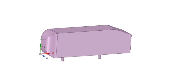
Ahmed's body is cut in half due to symmetry. The dimensions of Ahmed body are as follows 389x288x1044 (mm).
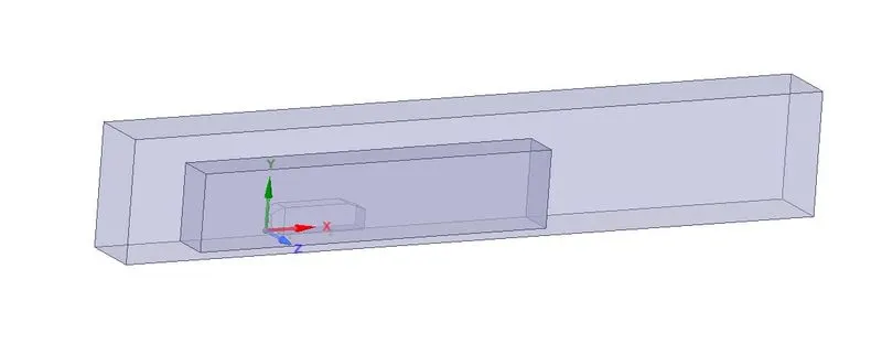
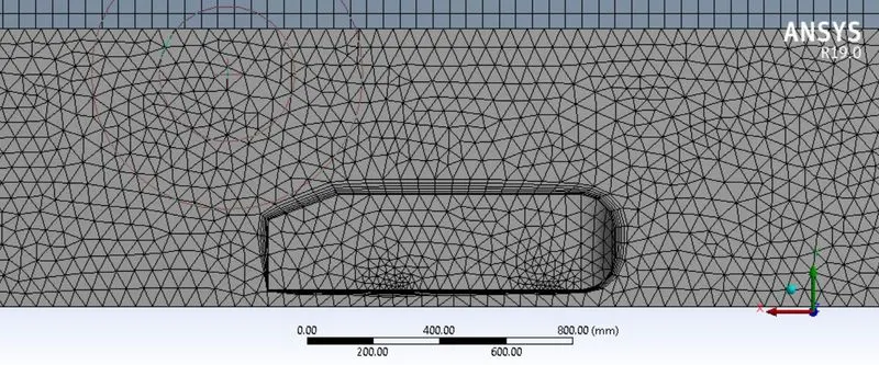
Creating a double enclosure for the Ahmed body and suppressing the original body for physics, followed by removing any interference from the interference tool.
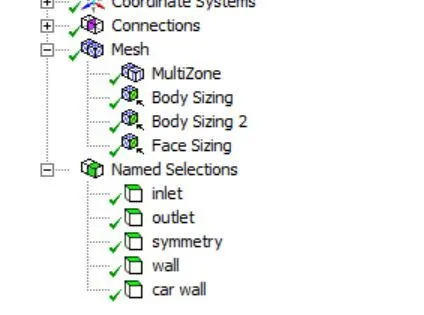
Named selections are provided, followed by the mesh method for multizone on the outer enclosure and mesh sizing of 45,50,55mm for the inner enclosure, followed by face sizing of 10mm for the stands of Ahmed body.
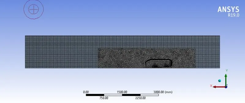
here inflation layer adds the accuracy to the result of drag force. y plus function is used to calculate the inflation layer thickness and layers.
Pre-processing and solver setting
A steady, pressure-based K-omega SST model is used for solving the problem. Reference values are calculated for the half body. if we want the drag coefficient for whole-body the area will be doubled leading to half of the coefficient of drag obtained.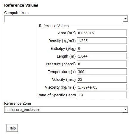
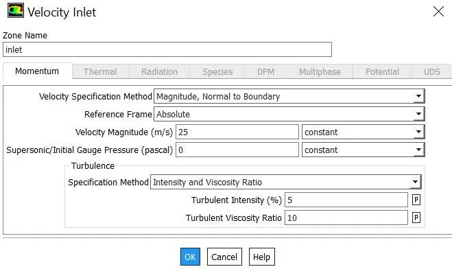
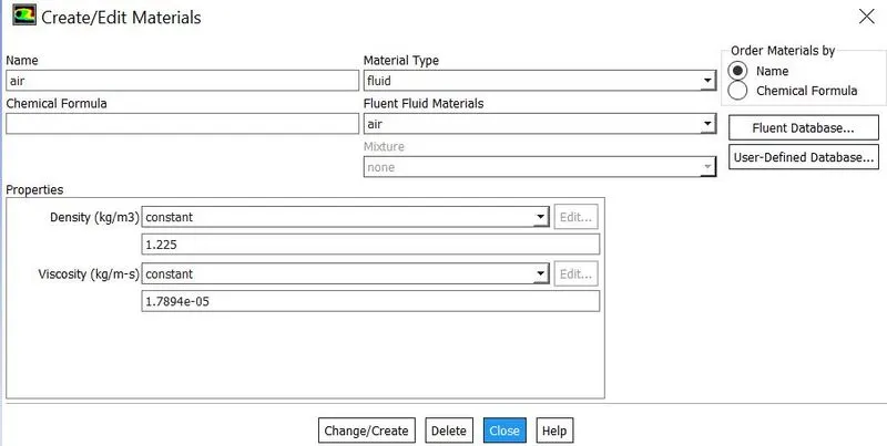
The material selected is air and the boundary condition for the inlet is 25m/s.
coefficient of drag report is generated for the car wall.
Initialize the solution and run for 500-600 iterations until the solution converges.
Results
1. Velocity and pressure contours
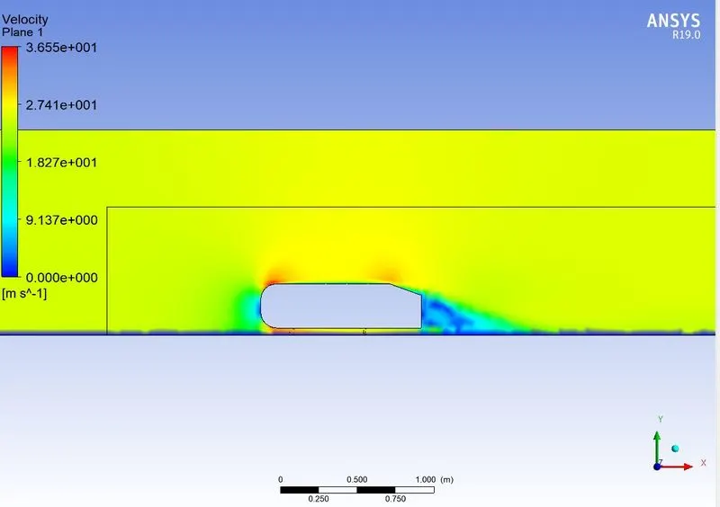
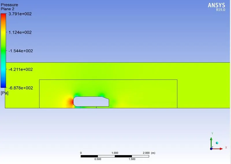
2. Drag coefficient
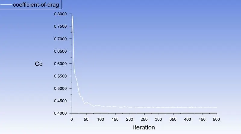
Found out to be around 0.425 for half body. when area is doubled(i.e. full body) the coefficient of drag is around 0.212.
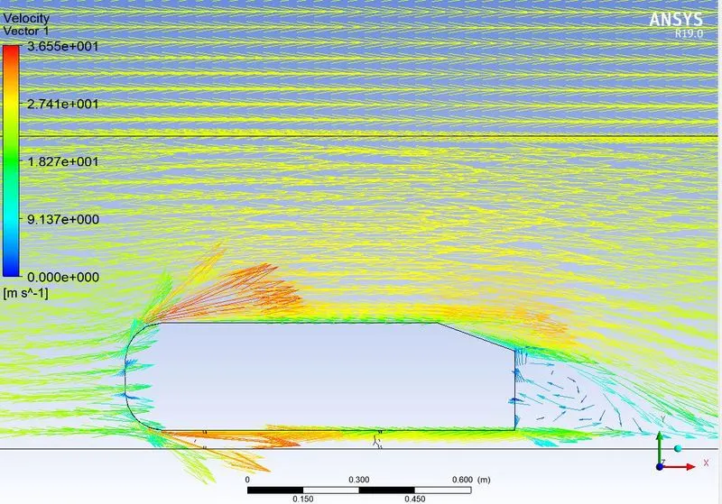
3. Vector plot for wake region
4. Grid Independence test
| Number of elements | Drag coefficient | Lift coefficient |
| 163654 | 0.212 | 0.162 |
| 217362 | 0.213 | 0.164 |
| 322546 | 0.212 | 0.163 |
Here we can note that the coefficients are independent of the element size and number of the element.
CONCLUSION
1. From running baseline simulation, the results were not correct, modifications in the mesh help in providing better and accurate results.
2. y+ functions give better results on turbulence modeling and reduce the chances of error in a conventional mesh.
3. Only on refining the mesh the wake region is captured properly.