Week 2 - Flow over a Cylinder.
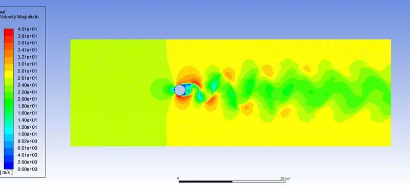
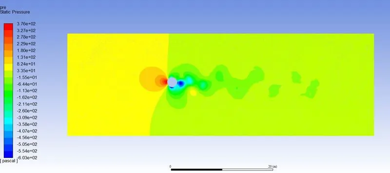
AIM - To simulate the flow over cylinder for different Reynolds numbers and explain the phenomenon of Karman vortex street.
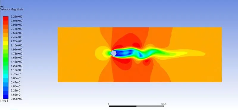
INTRODUCTION - Von Karman vortex sheet is a repeating pattern of swirling vortices, caused by vortex shedding. which causes separation of flow around the bodies. this can only be seen if the flow is above a certain Reynolds number. Reynold number is the ratio of inertial to viscous forces in a flow.
It is denoted by Re. Re= (`rho``xx`V`xx`D)/`mu`
where the symbols mean as follows
`rho`= density(1kg/m^3)
V = velocity
D = diameter of body(2m in the geometry used)
`mu` = Dynamic viscosity(0.05 kg/m.s)
Strouhal number is a dimensionless number describing the oscillating flow mechanisms. Denoted by St.
St = (f`xx`L)/U
f = frequency of vortex shedding
L = characteristic length
U = flow velocity
SOLVING AND MODELLING APPROACH
1. In Ansys workbench use the FLUENT tab and open geometry. Spaceclaim window will open. draw a circle of 2m diameter and a bounding box of dimension 60m X 20m. Use the pull tool to convert the geometry into the surface.
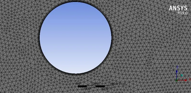
2. Open meshing and use the triangular elements instead of the quadrilateral elements. Select sizing a apply it to the body with an element size of 100mm. Also, select the edge sizing for the wall of the cylinder and give 36 subdivisions on it. each division for 10 degrees of the circle.
3. Use the inflation tool to create a body-fitted mesh and the size of each layer as 5mm, with 6 layers in total.
4. Open the fluent window and select parallel processing with 2 processors and double precision.
5. Check the mesh, use steady, Pressure based and absolute velocity model.
6. select the laminar model in the viscous flow modeling.
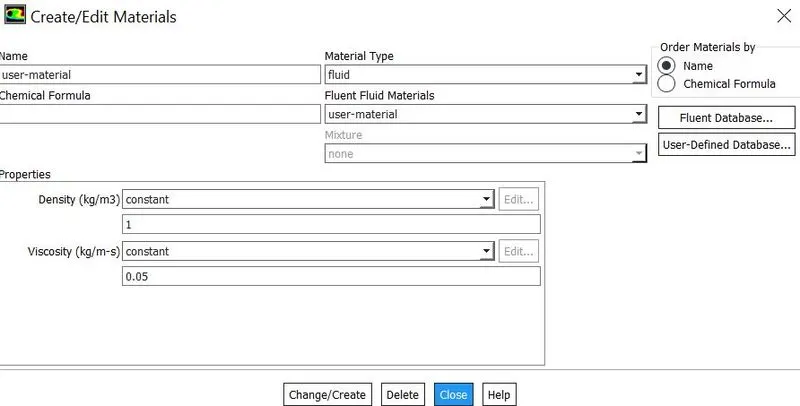
7. Define user material with a density of 1kg/m^3 and dynamic viscosity of 0.05kg/m.s.
8. cell zone material is changed to user-defined from the air.
9. Boundary conditions on the inlet to be given for different Reynolds numbers.
Reynolds number
- 10 - 0.25m/s
- 100 - 2.5m/s
- 1000 - 25m/s
- 10000 - 250m/s
- 100000 - 2500m/s
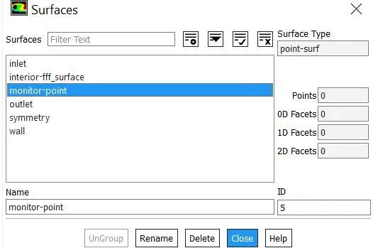
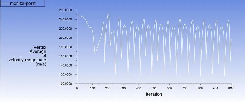
10. Create a monitor point 8m behind the cylinder.
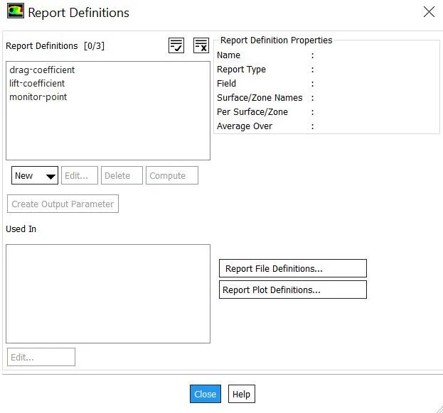
11. Generate reports for the coefficient of lift, coefficient of drag, and velocity at the monitor point.
12. Turn off the convergence at the residuals.
13. Initialization - use hybrid initialization. Plot the contours for the velocity and pressure, animation for the velocity at every 10 iterations.
14. Calculate for 1000 iterations.
PRE-PROCESSING AND SOLVER SETTING
New material
Reports generated
Total Surfaces
RESULTS
For Re = 10
Residuals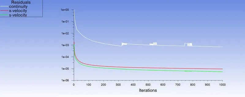
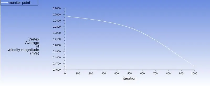
Velocity at the Monitor point
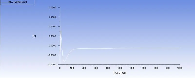
Coefficient of lift
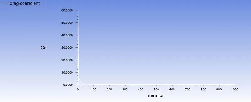
Coefficient of Drag
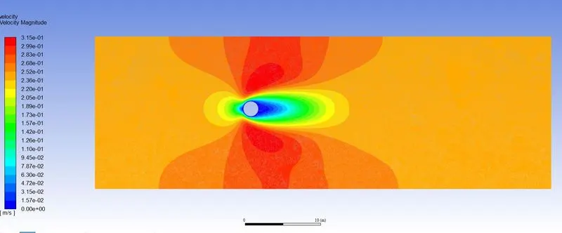
Velocity contour
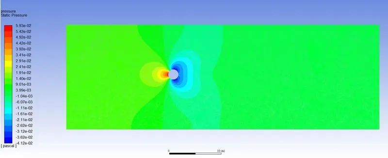
Pressure contour
For Re = 100
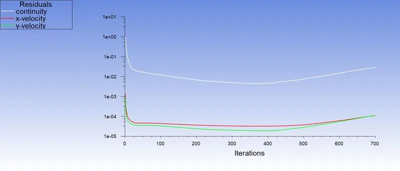
Residuals
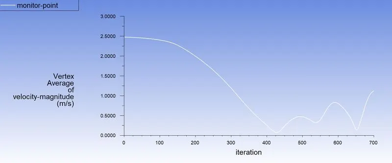
Velocity at the Monitor point
Coefficient of lift
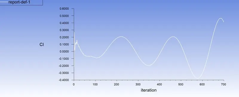
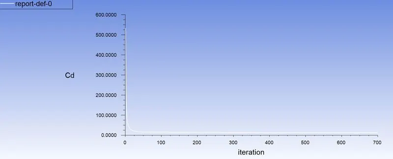
Coefficient of drag
Velocity contour
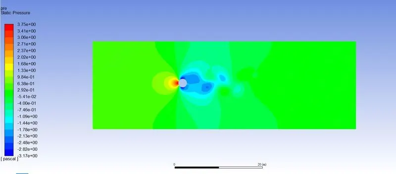
Pressure contour
For Re = 1000
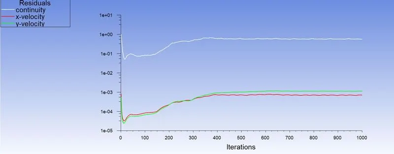
Residual
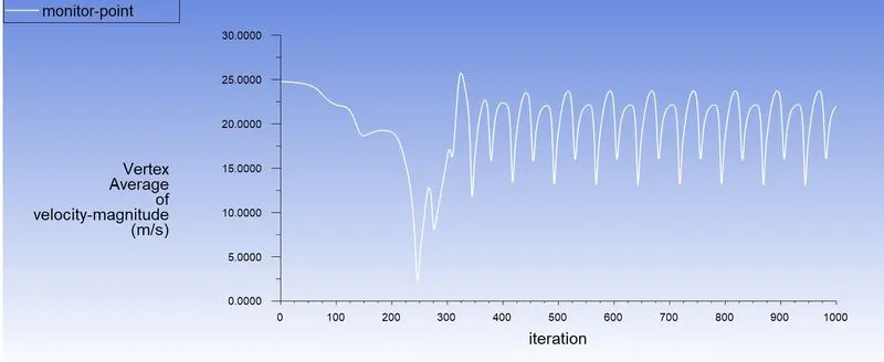
Velocity at the Monitor point
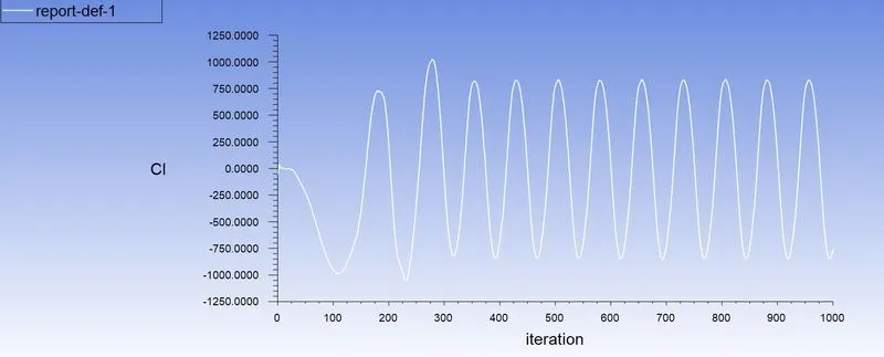
Coefficient of Lift
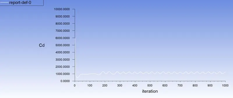
Coefficient of Drag
Velocity Contour
Pressure Contour
For Re = 10000
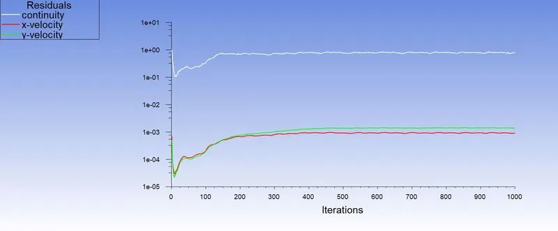
Residuals
Velocity at the Monitor point
Coefficient of Lift
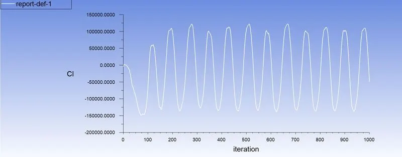
Coefficient of Drag
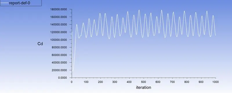
Velocity contour
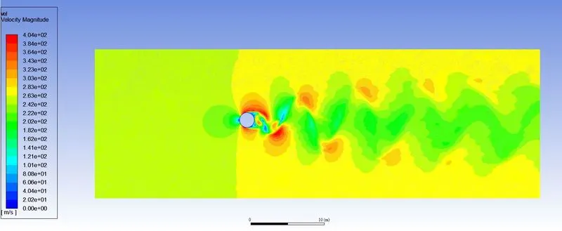
Pressure contour
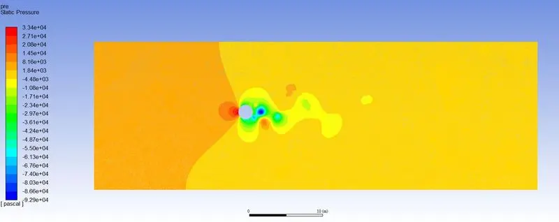
For Re = 100000
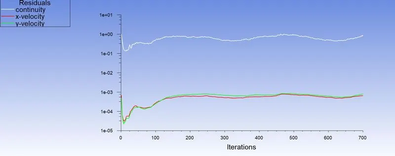
Residuals
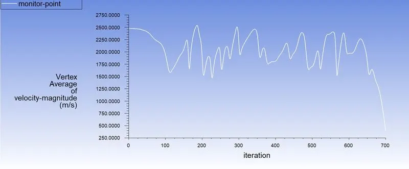
Velocity at the Monitor point
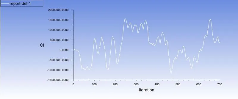
Coefficient of Lift
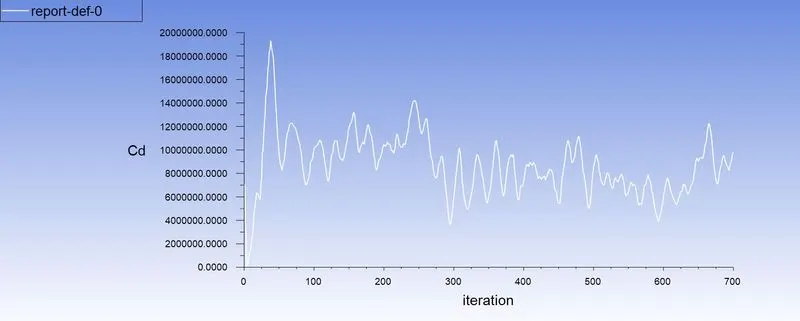
Coefficient of Drag
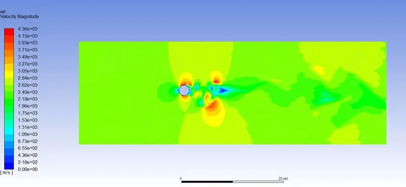
Velocity contour
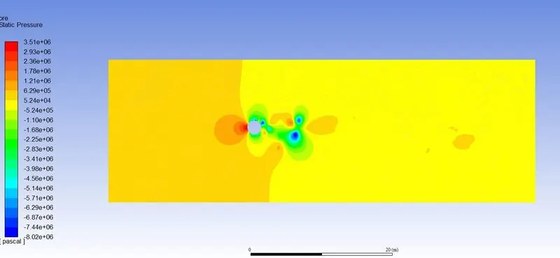
Pressure contour
CONCLUSIONS
1. The effect of Renolds number on the coefficient of drag is that it increases with increment in Reynolds number.
2. The value of strouhal number for Re = 100 is 0.0281.
VALIDATION
Reference Research Paper:- https://www.sciencedirect.com/science/article/pii/S0307904X08000243