Week 3 - External flow simulation over an Ahmed body.
Aim : To perform external flow simulation over an Ahmed body.
Ahmed body :
- The Ahmed Body was first created by S.R. Ahmed and it is used as research model which is the representation of the car.
- It is the benchmark model which is widely used in automotive industry for validating simulation tools.
- Ahmed's body, with its extremely straightforward design, enables us to capture distinctive elements significant to bodies in the automotive sector.
- The turbulent flow field surrounding a shape resembling an automobile is similarly described by means of this model. The numerical model is used to create new car models after it has been validated.
Procedure :
1. Load the Ahmed body file in Ansys claim.
2. Create a wind tunnel by enclosure option in Prepare tab. Uncheck the symmetric option and give the dimensions.
3. Create another box using the enclosure option and give the dimensions for that box.
4. Select a plane perpendicular to the Ahmed body to check the cross-section view.
5. Suppress the physics for the Ahmed body alone.
6. Check for interference and clear the interference which will separate the outer box from the inner box and also the Ahmed body from the inner box.
7. Three parts will not be interfering with each other so the mesh will not overlap each other and it will be uniform.
8. Open Mesh module, Click on mesh option on the left side & Click generate mesh to apply mesh.
9. Give different mesh for the different cases.
10.Give names for the wind tunnel and also the Ahmed body.
11.Use F8 to hide the side to select the Ahmed body to give the name.
12. To refine the mesh, right click mesh and select method and choose multi zone.
13. Give finer mesh for the inner box by selecting body sizing option and generate the mesh.
14. For the Ahmed body, give more finer mesh with the inflation layer so that the external flow can be accurate.
15. After giving the mesh values move to the Setup section to setup the physics.
16. In Setup section, Choose Density based solver, velocity formulation as Absolute and Time as Steady.
17. In Physics section, choose Energy equation and viscous as "k-epsilon".
18. Choose the material as "Air".
19. Give the values for the boundaries and give the velocity value as 25m/s.
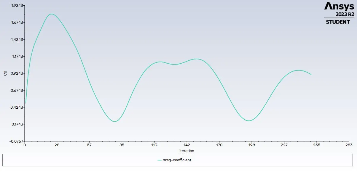
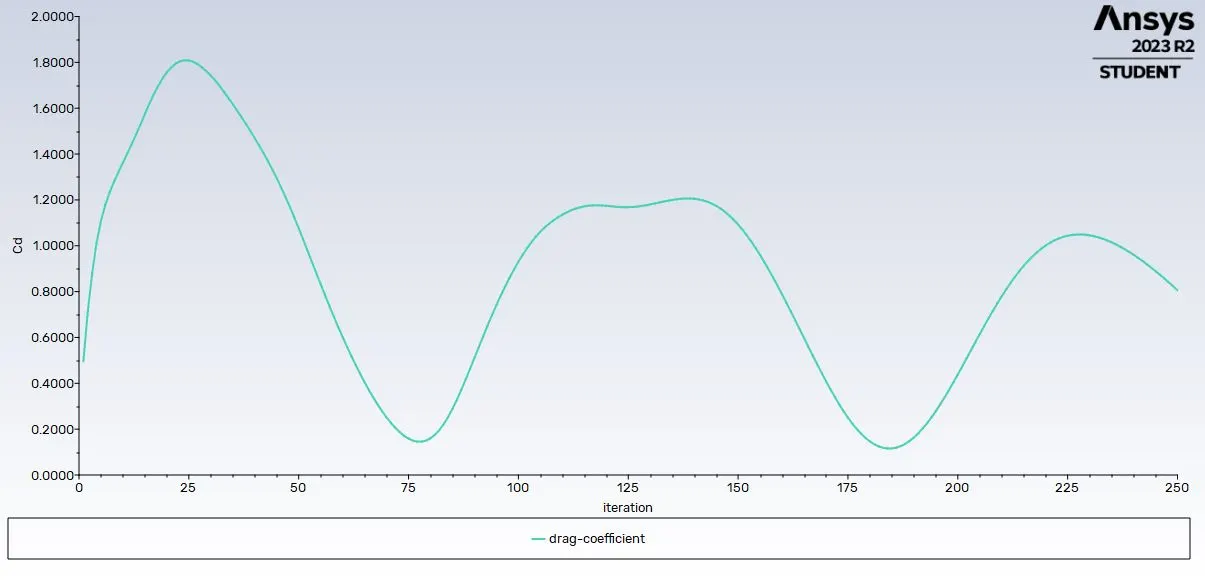
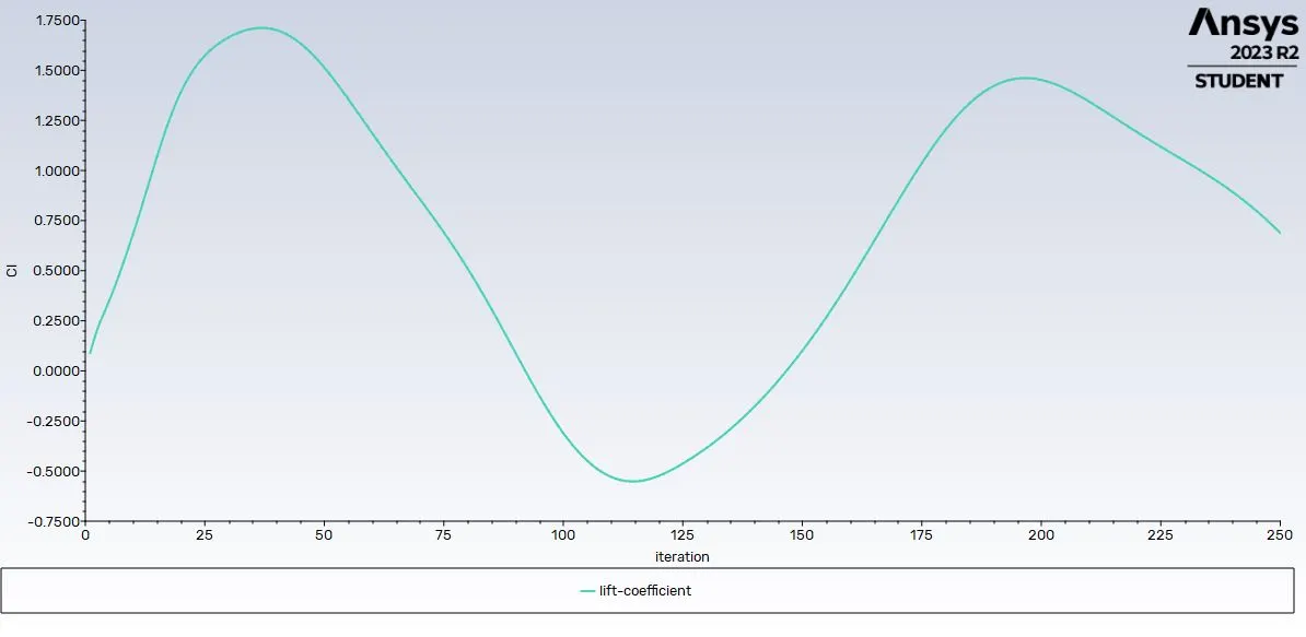
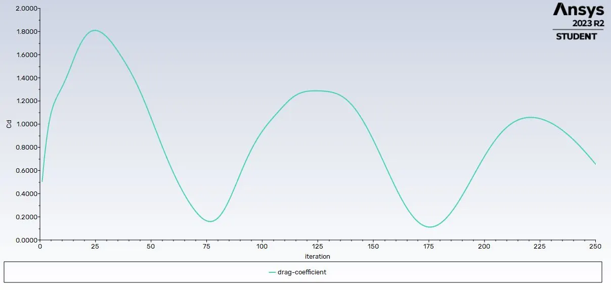
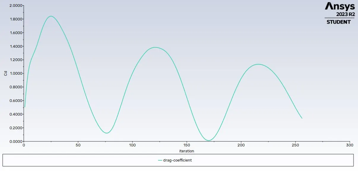
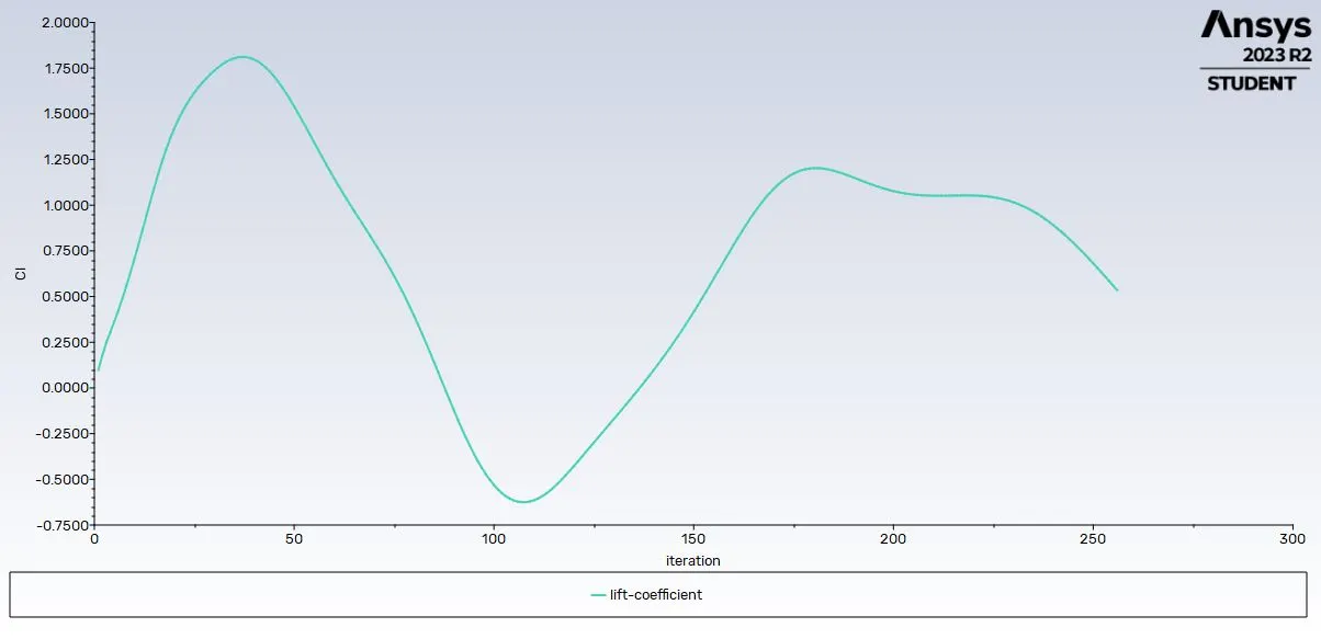
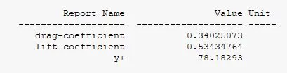
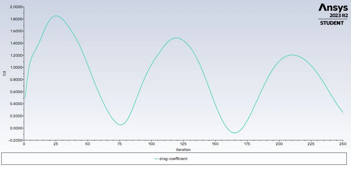
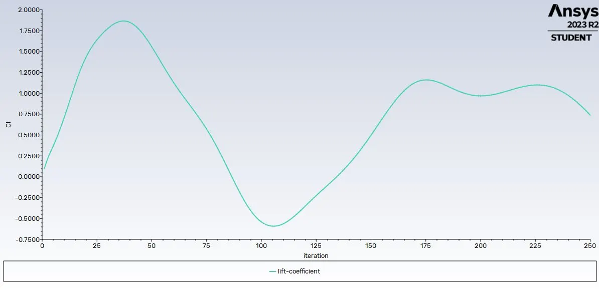
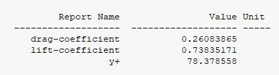
20. In Solution tab, generate report for drag & lift.
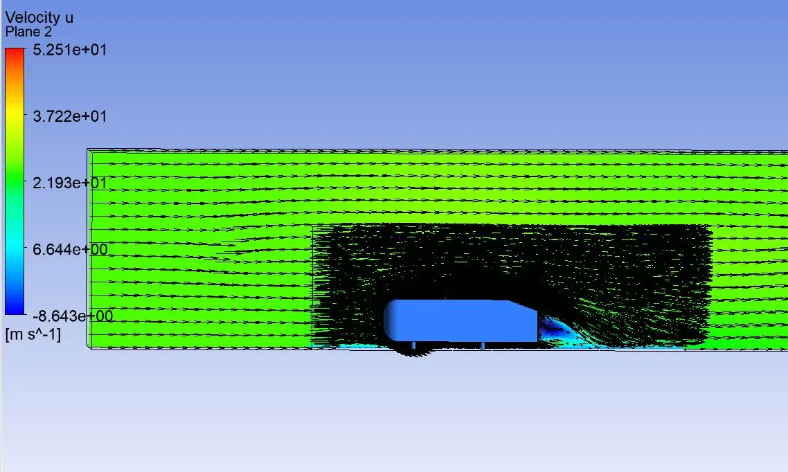
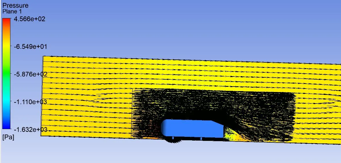
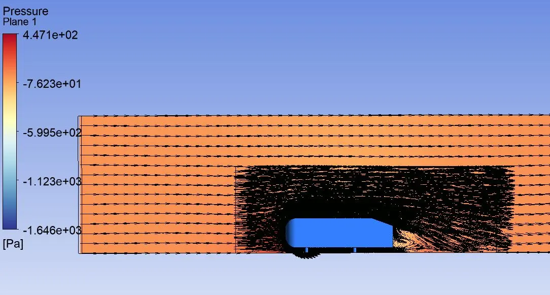
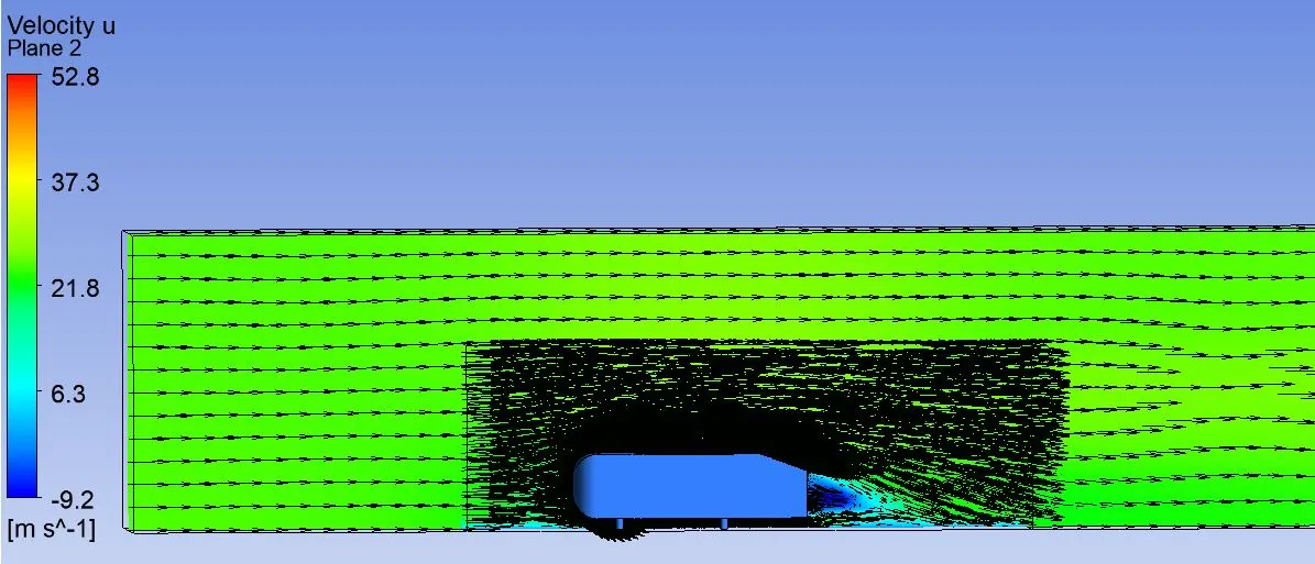
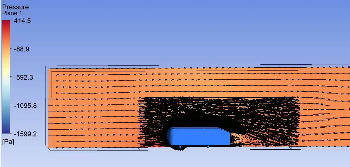
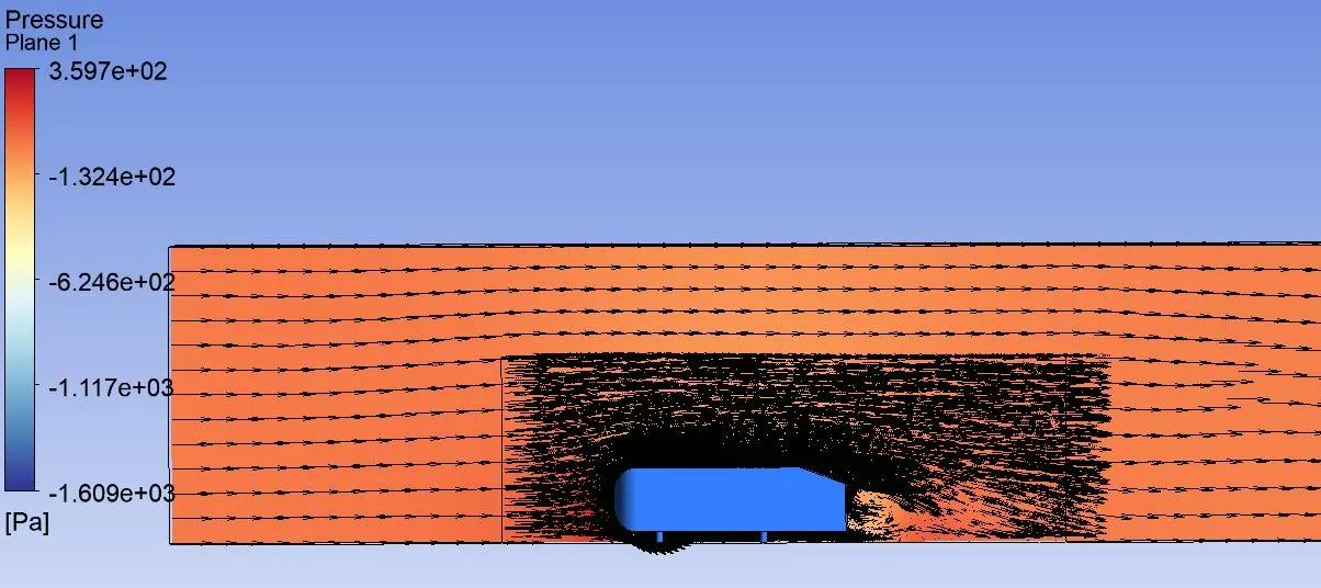
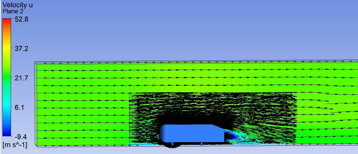
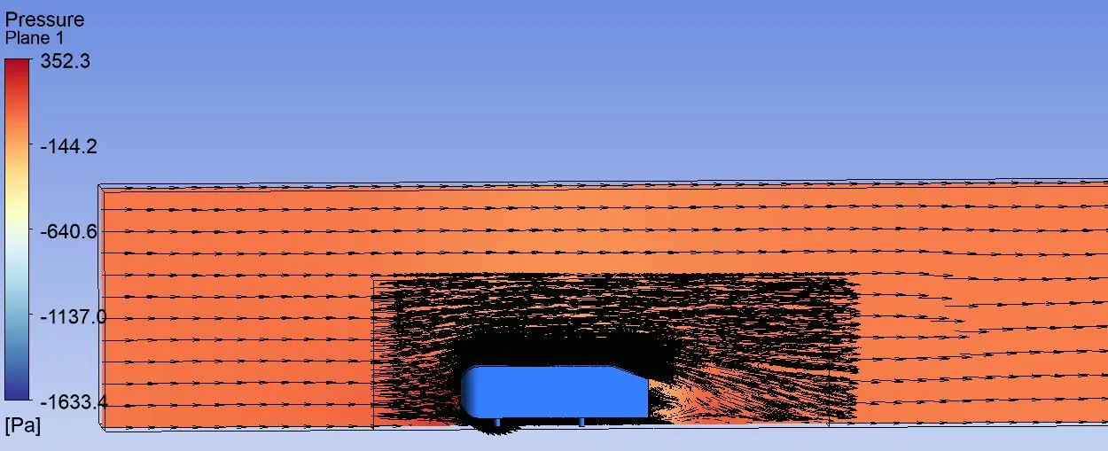
21. In results tab, generate pressure and velocity contours.
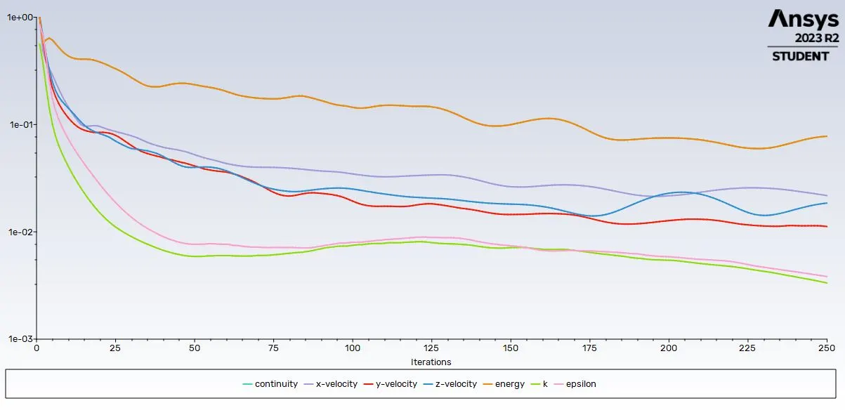
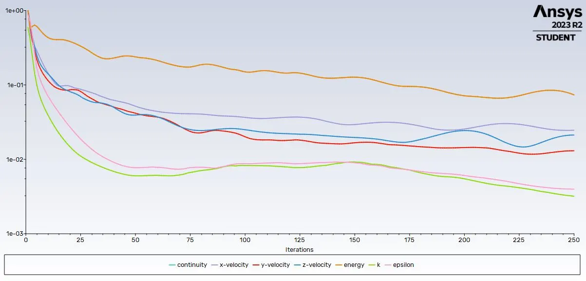
22. Choose Hybrid initialization and give no. of iterations as "250".
23. After the iteration, do the same process from Step 12-22 with the different mesh length.
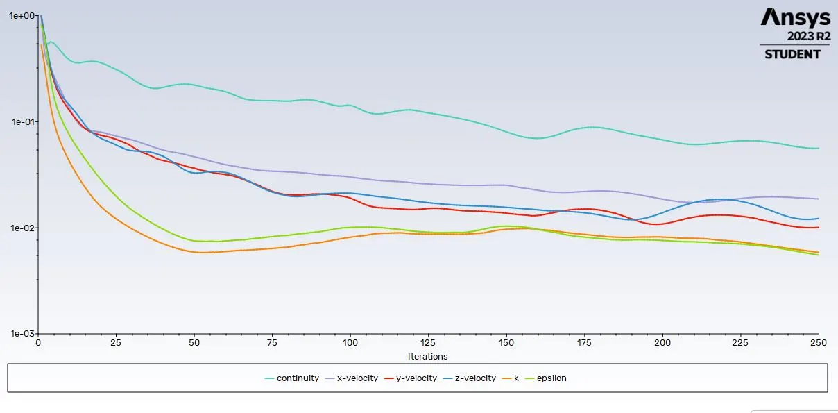
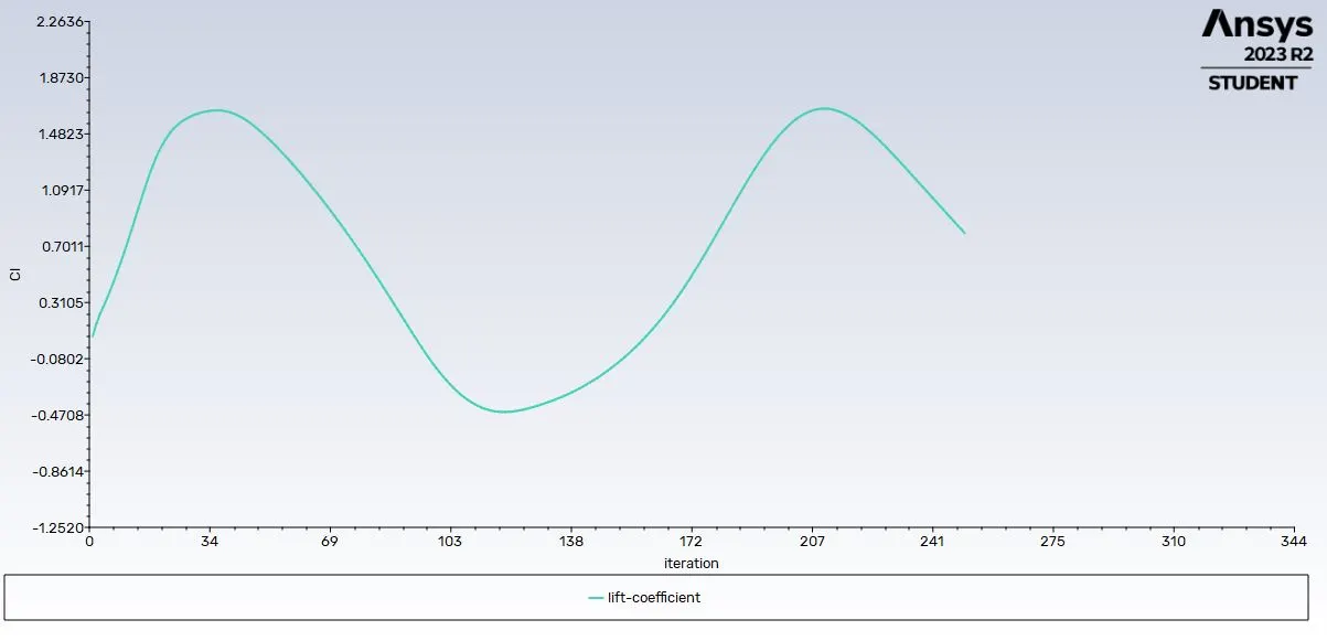
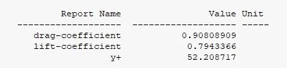
Case 1 :
- Outer mesh = 90mm
- Inner mesh = 45mm
- Inflation total thickness = 10mm (Max)
- Ahmed body mesh = 10mm
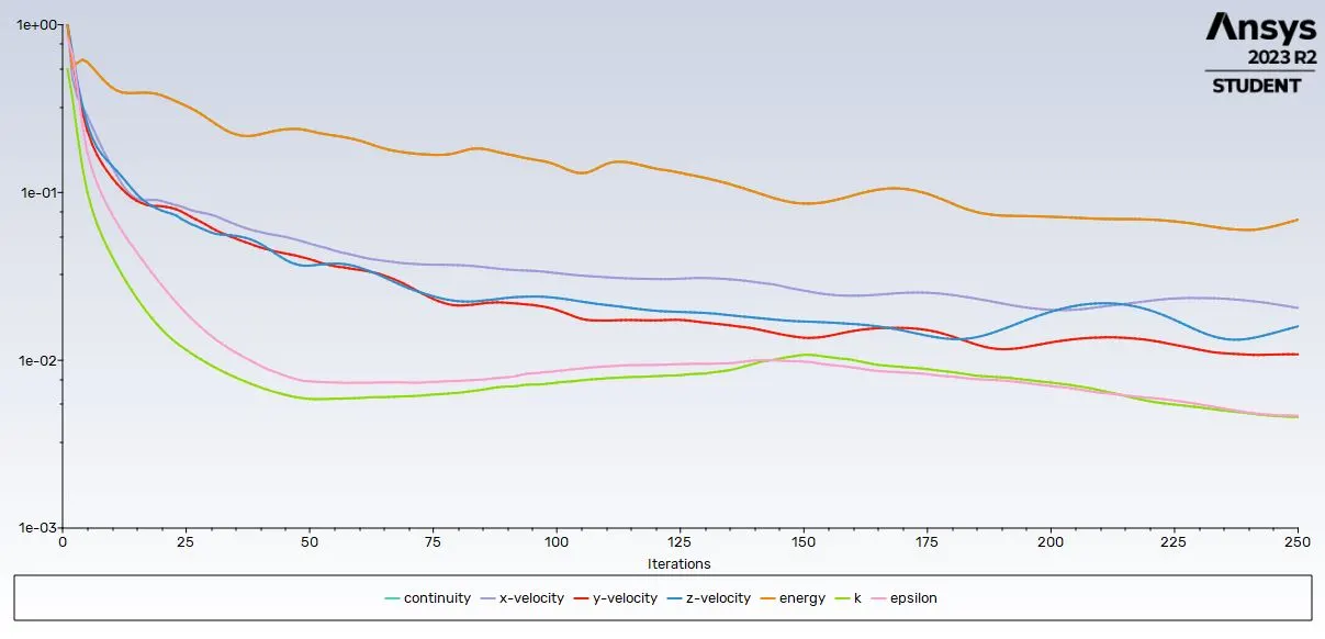
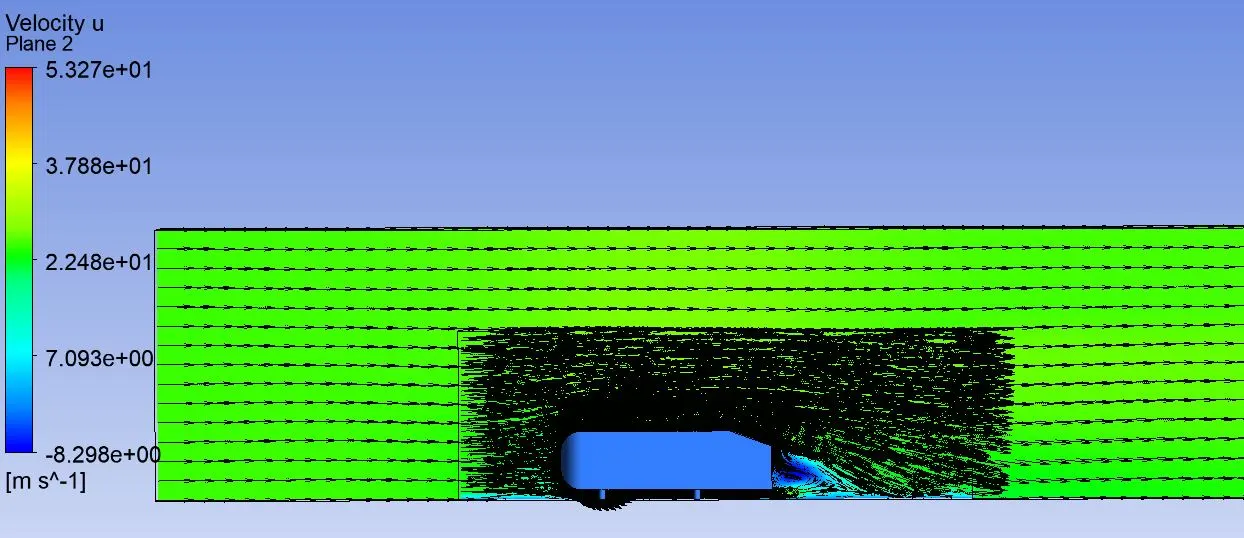
Case 2 :
- Outer mesh = 100mm
- Inner mesh = 50mm
- Inflation total thickness = 12.5mm (Max)
- Ahmed body mesh = 10mm
Case 3 :
- Outer mesh = 110mm
- Inner mesh = 55mm
- Inflation total thickness = 15mm (Max)
- Ahmed body mesh = 10mm
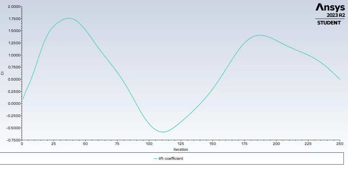
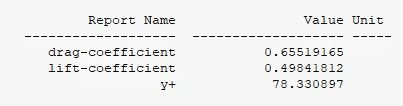
Case 4 :
- Outer mesh = 120mm
- Inner mesh = 60mm
- Inflation total thickness = 15mm (Max)
- Ahmed body mesh = 10mm
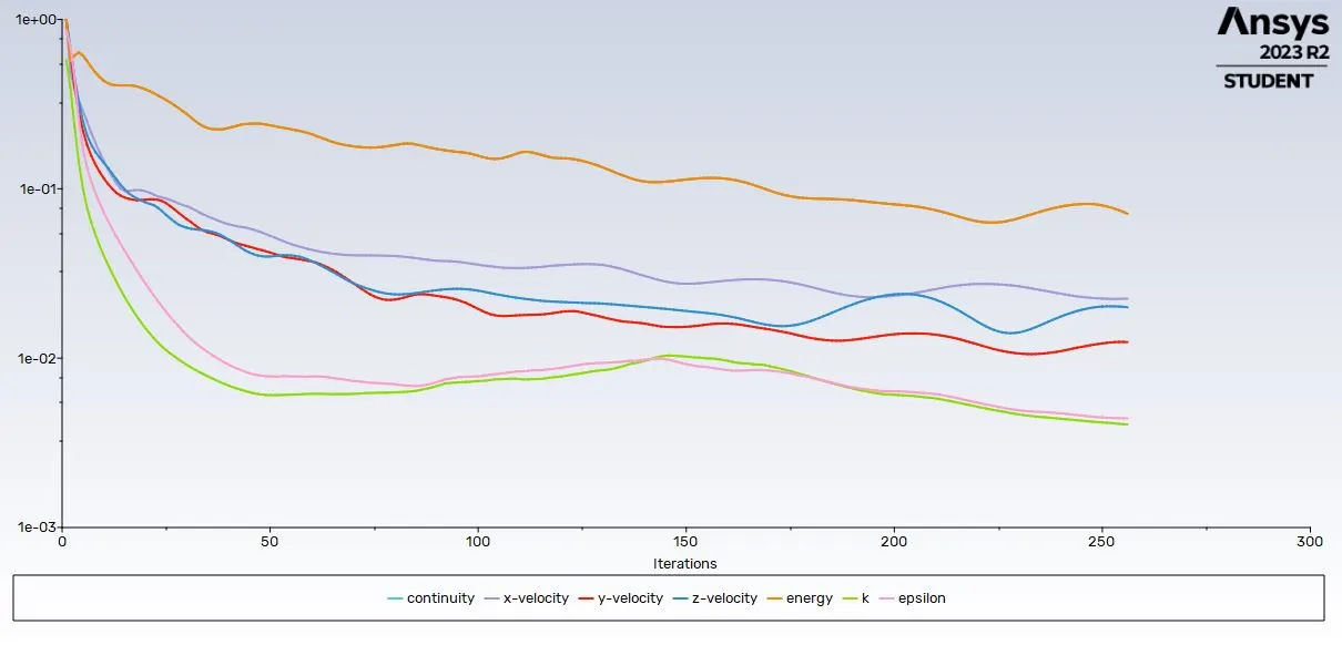
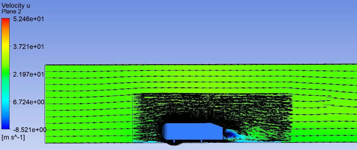
Case 5 :
- Outer mesh = 130mm
- Inner mesh = 65mm
- Inflation total thickness = 15mm (Max)
- Ahmed body mesh = 10mm
Conclusion :
1. The mesh which is generated with default mesh length gives coarse output hence we go for finer mesh.
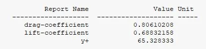
2. For k-epsilon, if the y+ values are greater than 50, we can get good results with error reduces significantly.
3. Point of separation is the point where the air stops sticking to the object or a car. This is where the shear stress becomes zero. The air molecules when attached to the body creates constant pressure and when the air separates the object then there will be sudden drop in pressure by increasing the drag pressure and reducing the lift force.
4. The negative pressure in the wake region is occurred due to the vortices formed after the point of separation hence velocity & pressure drops and thereby increasing the drag force.