Week 3 - External flow simulation over an Ahmed body.
Aim:- To simulate the flow over an Ahmed body using Ansys fluent.
Objective:-
- Creating an computational domain for the model in Spaceclaim.
- Mesh this domain as per the required cases.
- RUn external flow simulation with air being the fluid at an inlet velocity on 25 m/sec.
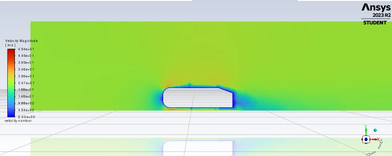
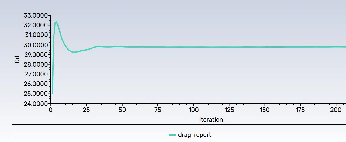
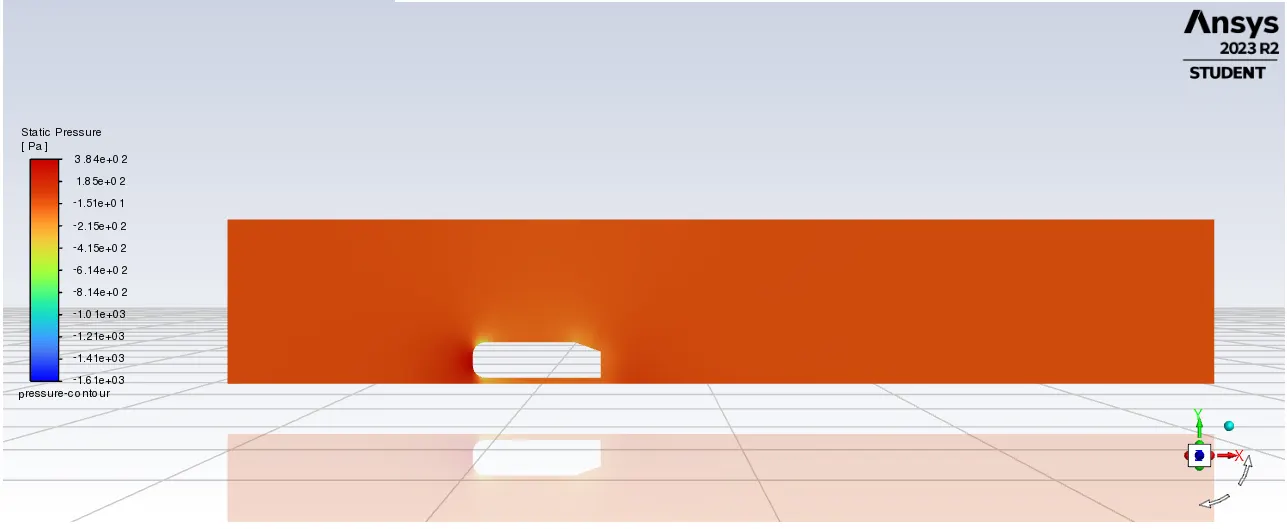
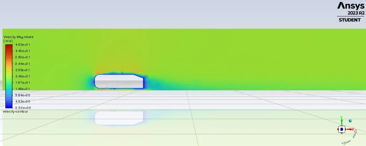
- Find the darg co-efficient and create the pressure and velocity contours.
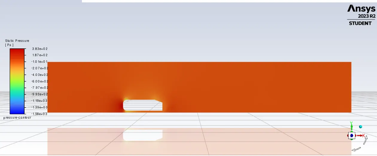
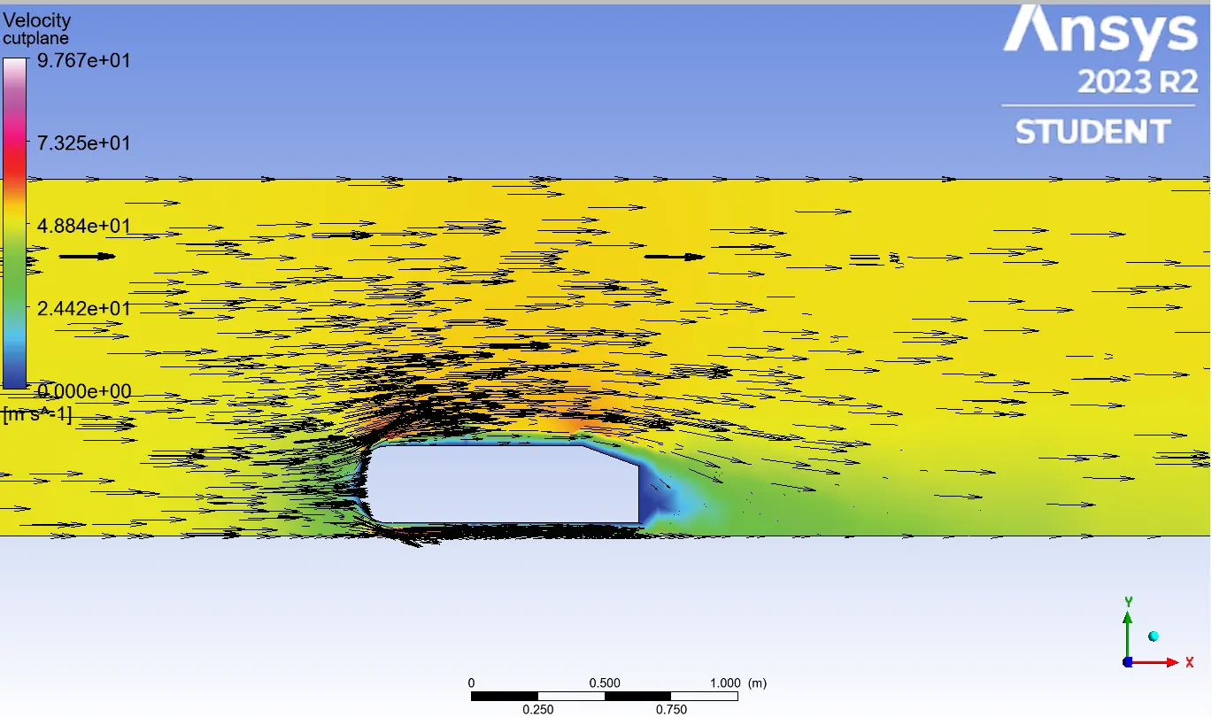
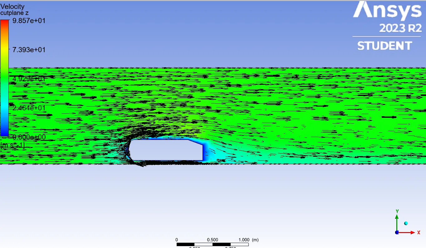
- Explaining the nevative pressure in wake region and significance of the point of seperation.
Ahmed Body:-
The Ahmed body, created by Dr. Ahmed M. Ahmed in the late 1970s, is a simplified geometric model used for aerodynamic testing, particularly in the automotive industry. It represents a generic car shape and has become a standard reference model for researchers and engineers studying the aerodynamics of ground vehicles. The Ahmed body is characterized by its simple, streamlined shape with a slanted rear end.
Key features of Ahmed's body include:-
1. Bluff Body Shape:- The body has a bluff (blunt) front end, simulating the front of a vehicle, and a slanted rear end that mimics the general shape of a car.
2. Inclined Rear Panel:- One distinctive feature is the inclined rear panel, which contributes to the body's characteristic aerodynamic properties.
3. Ground Proximity:- The body is typically positioned close to the ground in wind tunnel testing to simulate the effects of the road on the vehicle's aerodynamics.
The importance of Ahmed's body lies in its role as a standardized model for studying and understanding the aerodynamic behavior of vehicles. Here are some reasons why it is significant:
1. Simplicity:- The Ahmed body provides a simple yet representative model for aerodynamic studies. Its geometric simplicity allows researchers to isolate and understand fundamental aerodynamic principles without the complexity of a real vehicle.
2. Cost-Effectiveness:- Wind tunnel testing can be an expensive process. The Ahmed body offers a cost-effective alternative to using detailed vehicle models, making it accessible for research and development purposes.
3. Comparative Studies:- Engineers and researchers use Ahmed's body as a benchmark for comparing the aerodynamic performance of different vehicle designs. This helps in identifying optimal shapes and design modifications to enhance fuel efficiency and stability.
4. Drag Reduction:- Understanding the drag forces acting on a vehicle is crucial for improving fuel efficiency. Ahmed's body allows researchers to explore ways to reduce aerodynamic drag, leading to more fuel-efficient and environmentally friendly vehicle designs.
In summary, Ahmed's body is a valuable tool in aerodynamic research, providing a standardized and cost-effective means of studying the airflow around vehicles. It has significantly contributed to the development of more aerodynamically efficient and fuel-efficient vehicles in the automotive industry.
Aerodynamic studies using models like the Ahmed body are crucial in the automotive industry to optimize vehicle design for fuel efficiency, stability, and overall performance. Researchers and engineers can use wind tunnel experiments and computational simulations to analyze the airflow around the Ahmed body and derive insights into how different car shapes can affect aerodynamic performance.
Wake region:-
In the context of aerodynamics and fluid dynamics, the term "negative pressure" refers to a pressure that is lower than the ambient pressure. The reason for negative pressure in the wake region of an object, such as a vehicle or an airfoil, is closely tied to the aerodynamic phenomena associated with the flow of air around the object.
When an object moves through a fluid, such as air, it disturbs the air molecules in its path. As the air flows over the surface of the object, it accelerates, and according to Bernoulli's principle, an increase in fluid velocity is associated with a decrease in pressure. This principle states that in a flowing fluid, an increase in the speed of the fluid occurs simultaneously with a decrease in pressure.
In the wake region behind an object, several factors contribute to the development of negative pressure:-
1. Acceleration of Air:- As air flows around the leading edges and over the surface of the object, it accelerates. According to Bernoulli's principle, this acceleration is associated with a decrease in pressure.
2. Vortices and Turbulence:- The flow of air around an object can lead to the creation of vortices and turbulence in the wake region. These swirling motions can further contribute to pressure variations, including negative pressure zones.
3. Separated Flow:- In some cases, especially when the airflow cannot follow the contours of the object's surface, the flow may separate from the surface. This can create low-pressure zones in the wake.
The negative pressure in the wake region is often referred to as "drag." Drag is the aerodynamic force that opposes the motion of the object through the fluid. While negative pressure in the wake contributes to drag, it's important to note that drag is a complex phenomenon influenced by various factors, including the shape of the object, the Reynolds number, and the angle of attack.
In summary, the negative pressure in the wake region is a result of the complex interactions between the object and the flowing fluid. Understanding these aerodynamic principles is crucial in designing vehicles and structures with improved efficiency and reduced drag.
In the context of Ahmed body simulation, the negative pressure in the wake region is primarily a result of the complex aerodynamic flow patterns around the geometric shape of the Ahmed body. The Ahmed body is designed with a specific geometry that induces a separated flow and vortex shedding in the wake region. This separation of flow and the generation of vortices contribute to the development of negative pressure.
Here are key reasons for negative pressure in the wake region of an Ahmed body simulation:
1. Flow Separation:- The bluff body shape of the Ahmed body, with its sharply inclined rear end, induces flow separation. As the air flows over the body, it cannot follow the surface contours perfectly, leading to separation of the flow from the body surface. This separation creates low-pressure zones in the wake.
2. Vortex Shedding:- The Ahmed body design promotes the shedding of vortices in the wake region. Vortices are rotating regions of air that can persist downstream of the body. These vortices create a complex flow field with regions of low pressure, contributing to the overall negative pressure in the wake.
3. Pressure Differentials:- The aerodynamic forces acting on the Ahmed body create pressure differentials. The geometry and flow conditions result in lower pressure in certain areas, particularly in the wake region. This negative pressure contributes to the drag force experienced by the body.
4. Aerodynamic Drag:- The negative pressure in the wake region is a manifestation of aerodynamic drag. Drag is the resistance encountered by a body moving through a fluid, and in the wake of the Ahmed body, this resistance is associated with lower pressure.
Understanding and analyzing the negative pressure in the wake region of an Ahmed body simulation are crucial for assessing the aerodynamic performance of vehicles. Researchers use such simulations to study how changes in the vehicle's design can influence drag, lift, and overall aerodynamic efficiency. The insights gained from Ahmed body simulations contribute to the optimization of vehicle shapes for improved fuel efficiency and stability.
Significance of point of seperation:-
The point of separation in fluid dynamics refers to the location on a surface where the airflow transitions from being attached to the surface to becoming separated. This separation point is crucial in understanding and analyzing the aerodynamic behavior of objects, such as airfoils, wings, and vehicle bodies. The significance of the point of separation lies in its impact on aerodynamic forces, pressure distribution, and overall performance. Here are some key aspects of its significance:
1. Aerodynamic Drag:- The point of separation is closely linked to the development of aerodynamic drag. When airflow separates from a surface, it creates a wake of turbulent air, contributing to drag forces. The location of the separation point influences the magnitude of drag, and minimizing drag is essential for improving the fuel efficiency of vehicles.
2. Pressure Distribution:- The point of separation is associated with changes in pressure along the surface of an object. Before separation, the pressure is generally higher, and after separation, it decreases. Understanding the pressure distribution helps engineers optimize the design of aerodynamic surfaces to achieve desired lift and drag characteristics.
3. Stall Phenomenon:- In aerodynamics, a stall occurs when the angle of attack of an airfoil is too high, and the airflow separates abruptly. This can lead to a significant decrease in lift and an increase in drag. Pilots and engineers carefully study the point of separation to avoid stalls and ensure safe and efficient aircraft operation.
4. Control of Separation:- Engineers and designers work to control or delay separation to improve aerodynamic performance. They may use techniques such as vortex generators, winglets, or changes in surface contours to manage the flow and delay separation, thereby optimizing lift and reducing drag.
5. Vehicle Stability:- The point of separation influences the overall stability and handling characteristics of vehicles. By understanding and controlling separation, engineers can design vehicles with better stability, especially at high speeds.
6. Efficiency and Performance:- Optimizing the point of separation is essential for enhancing the overall efficiency and performance of vehicles, aircraft, and other objects moving through a fluid. Efficient aerodynamics contribute to reduced fuel consumption, improved speed, and better control.
In summary, the significance of the point of separation lies in its direct impact on aerodynamic forces, pressure distribution, and the overall performance of objects moving through a fluid. Engineers and researchers carefully analyze and manipulate the point of separation to achieve desired aerodynamic characteristics and enhance the efficiency and safety of various vehicles and systems.
Simulation:-
Case-1:-Creating a flow simulation around the Ahmed body
Geometry:-
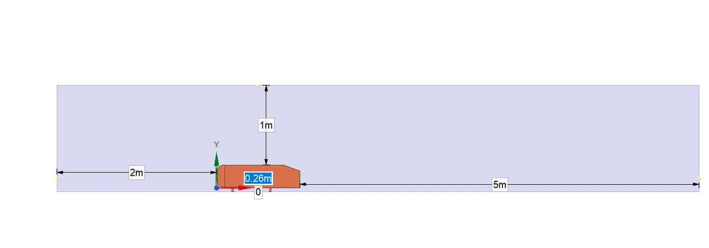
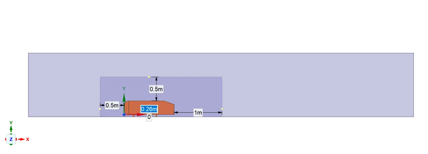
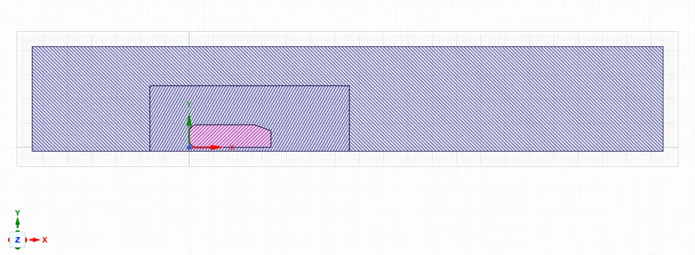
Here we will a region of refinement right in front and wake region since the result around the Ahmed body will be unresolved or there will not be lot of mesh point, so to avoid this, we will creat one more enclosure and make the mesh more finer in this region. This is also called local refinement.
To make one more region, we have used enclosure command once more.
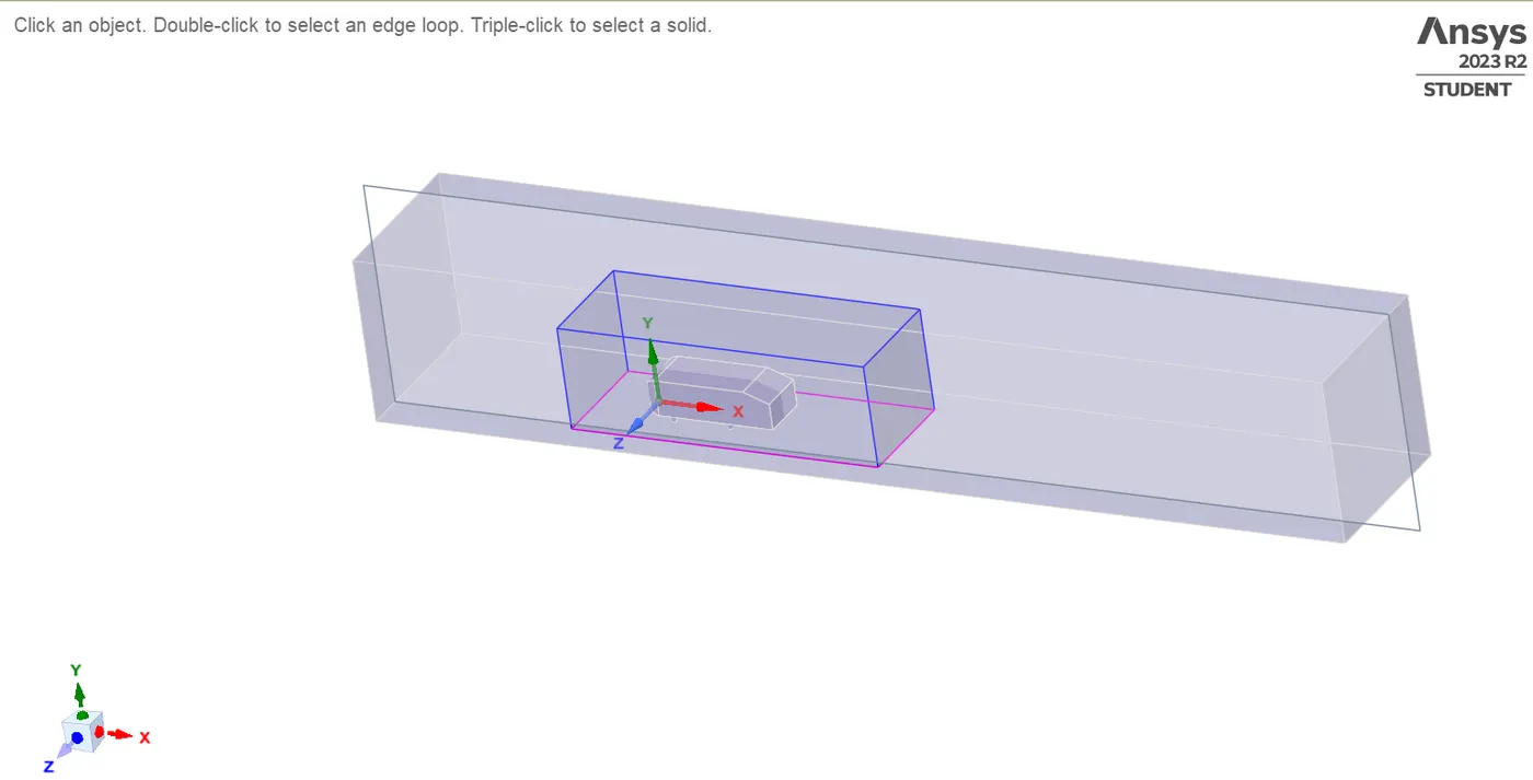
In section mode, we have interference fit as shown in image below
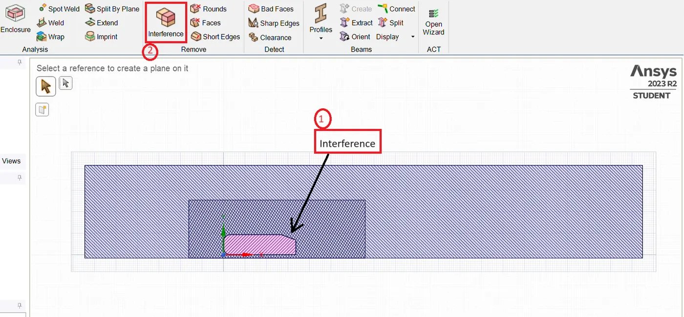
To avoid this, we will go into Prepare -> interference. This wil will give us interference prompt as shown
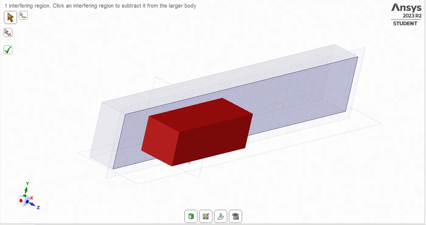
On clicking the complete icon, this problem gets resolved and we get
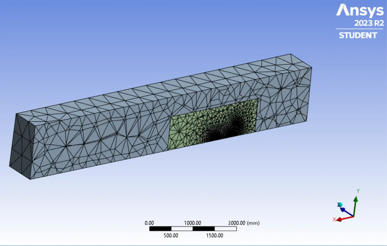
Mesh:-
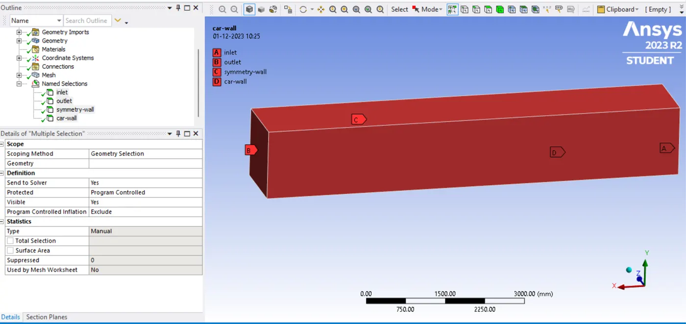
Providing the name section to the faces
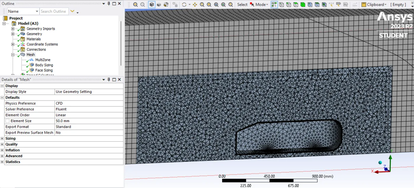
Giving MultiZone, Body Sizing and face sizing in mesh
Solver:-
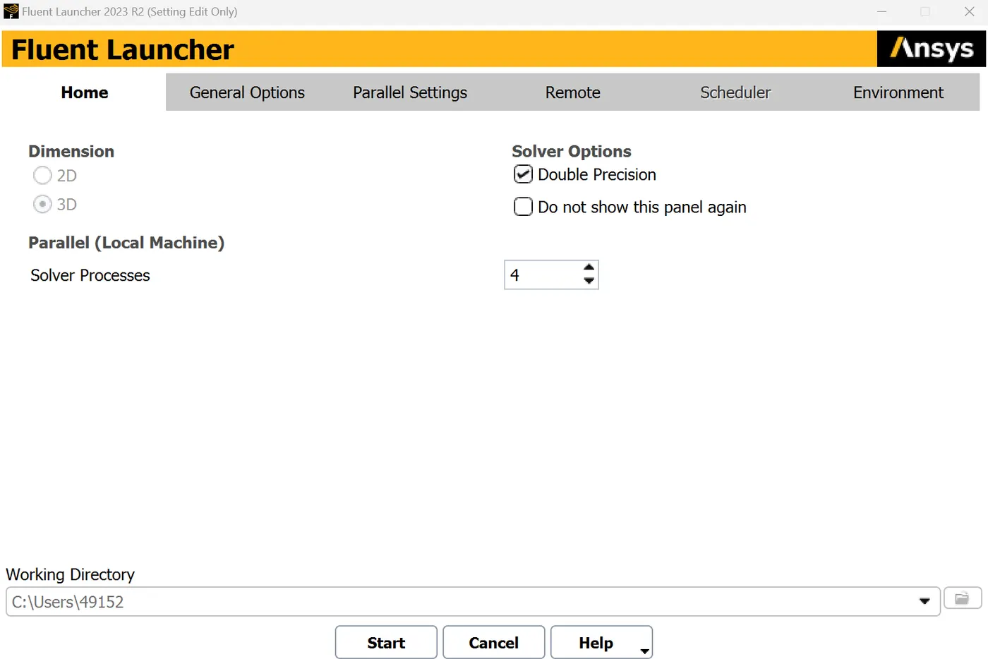
Launching the fluent solver with 4 processes and double precision
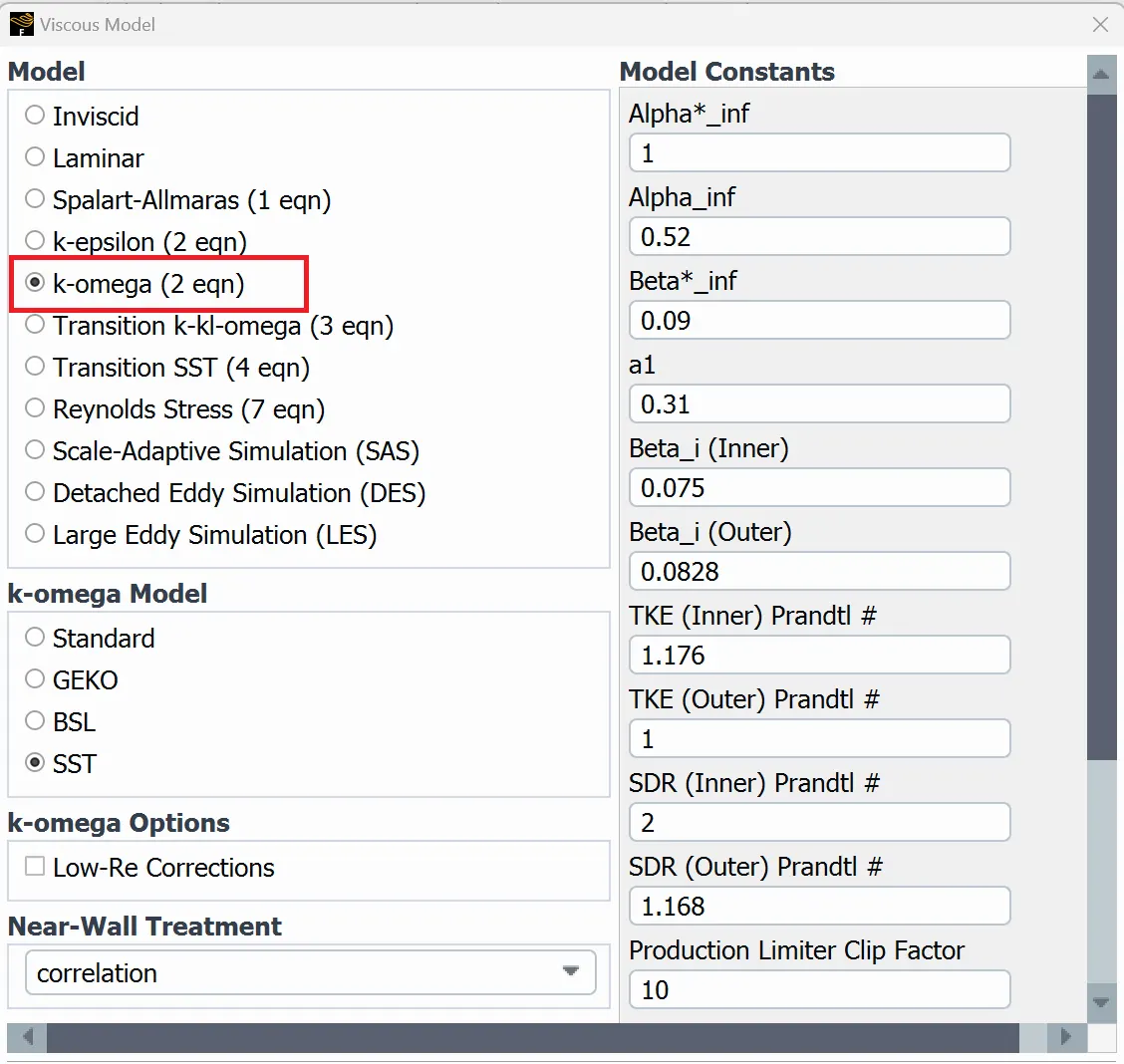
We are using k-omega for this problem.
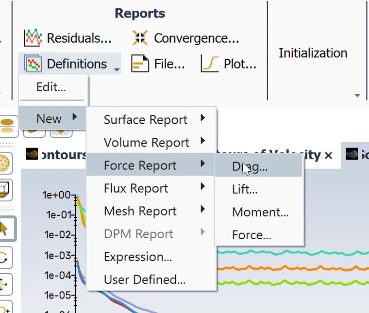
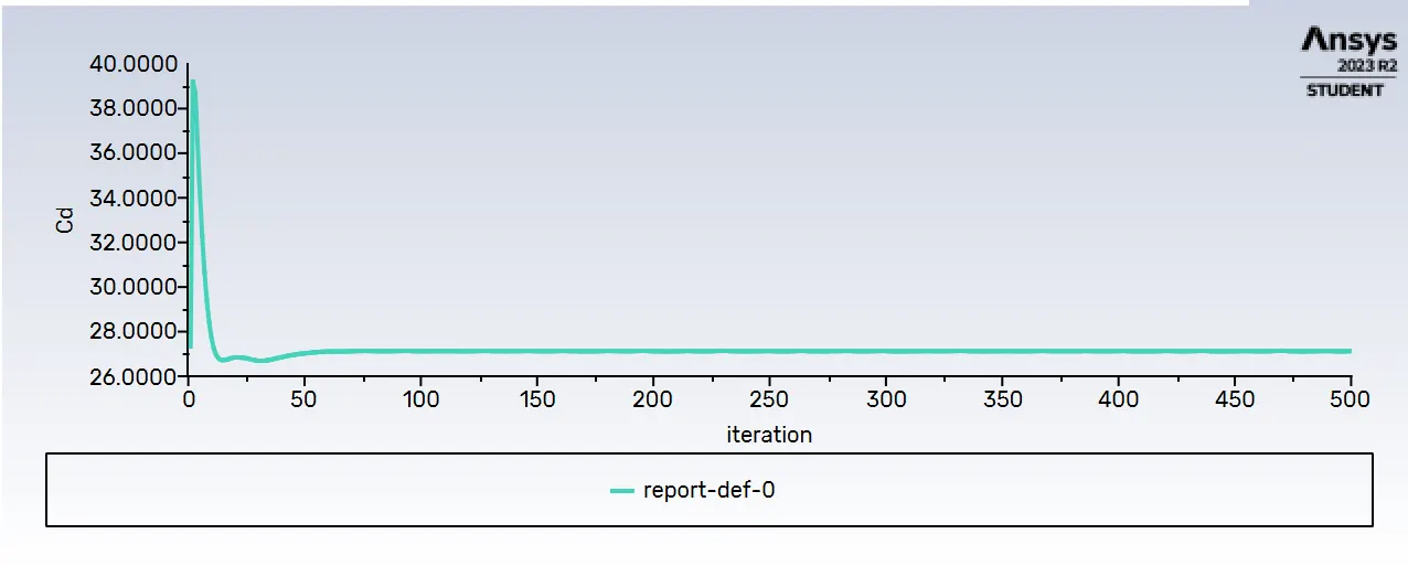
for drag,we go into Solution -> Defination -> New -> Force report -> Drag
Material used is air
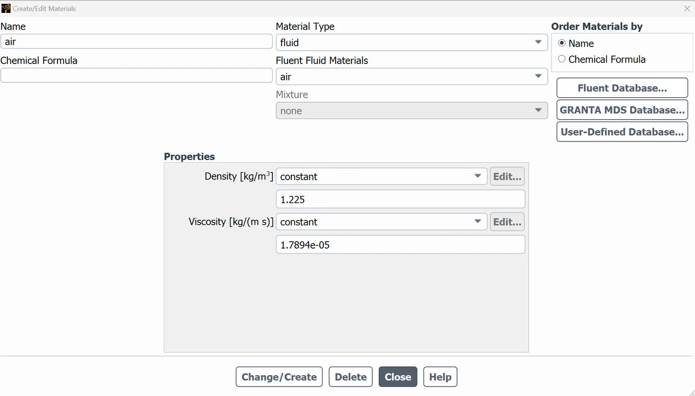
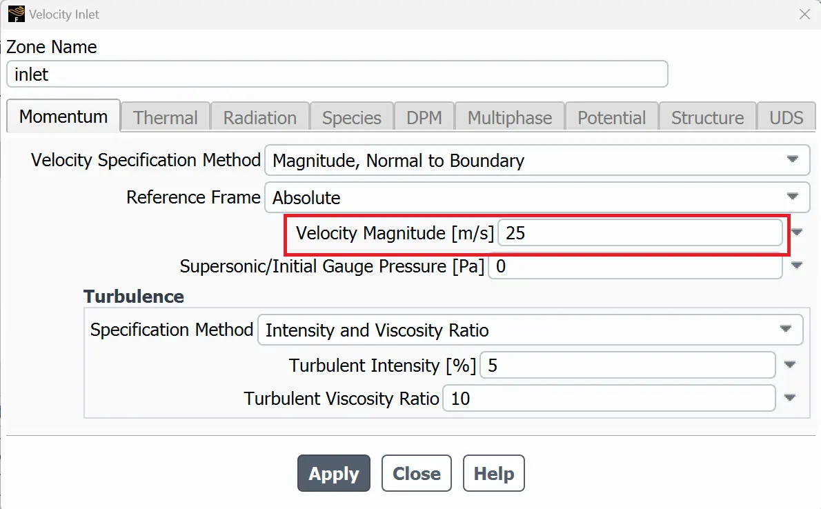
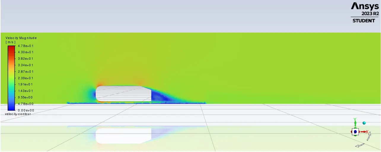
Assigning the boundary condition as 25m/s at inlet
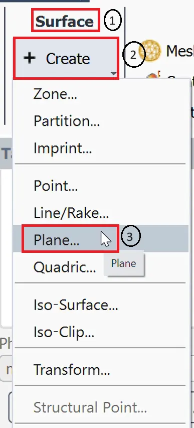
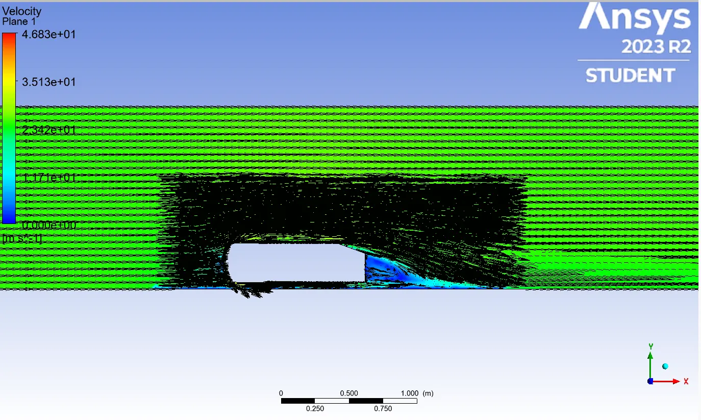
Creating a plane from Result -> Surface -> Plane
- After the physics part is done move to the solution part. Initialise the simulation first. click Initialize to initialize the boundary conditions. Hybrid method is selected before initialization. Click on Autosave to obtain a animation of the flow in the post results.
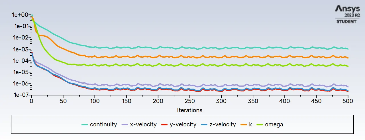
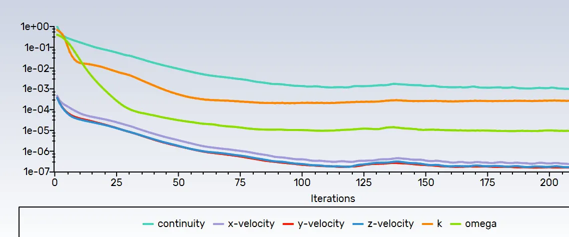
- Then run the calculation for a given number of iterations till the convergence is obtained. Depending upon the number of elements and model selected the time required for convergence varies. In the CFD module itself we can compute, measure, plot, animate, etc., if needed.
- After the solutions and calculations move to the result module to get different graphs, plots, contours, animations etc.,. Sectional views can be created if required.
Result:-
Case 2:-
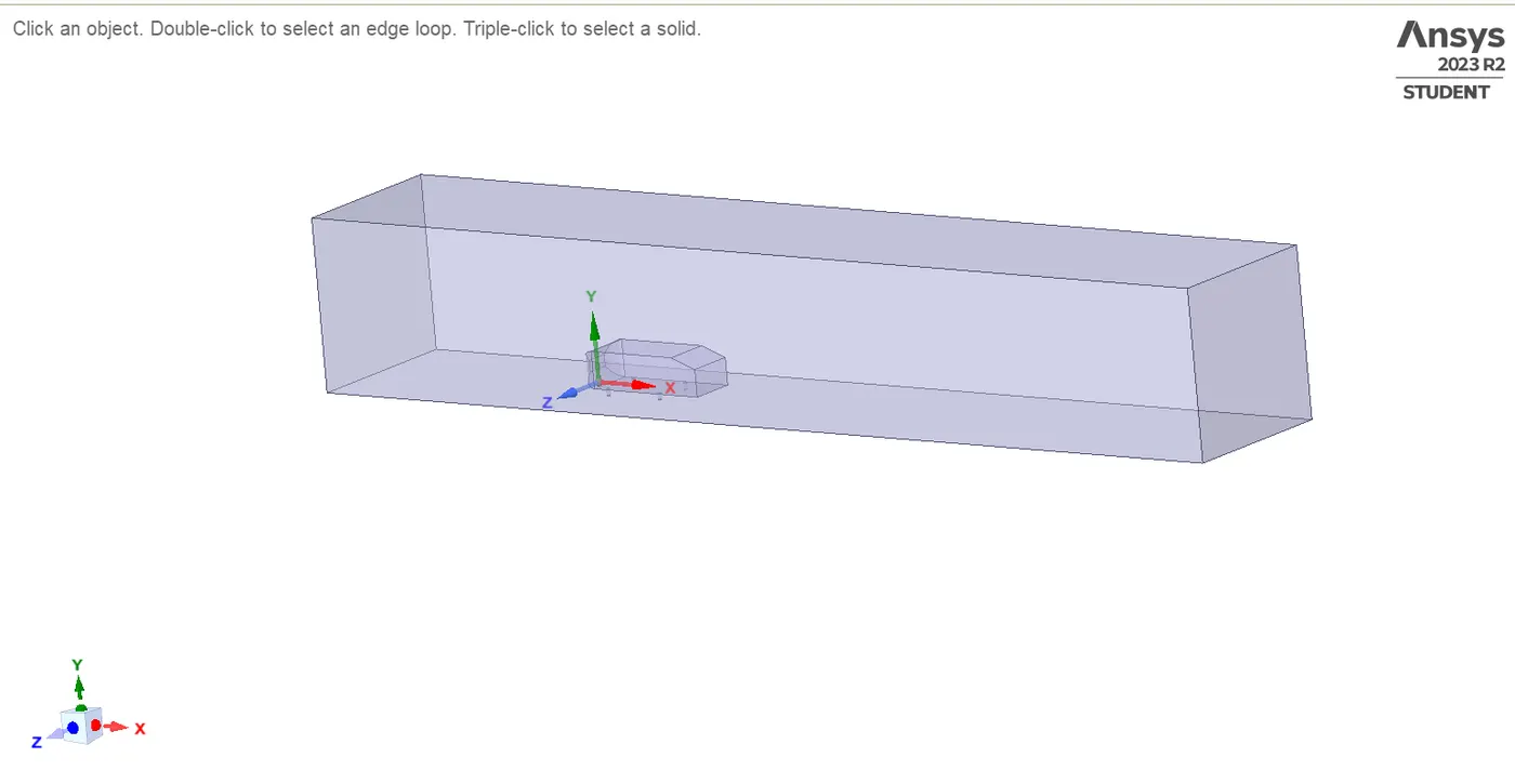
Following the able steps as it is with only difference that here we wont be creating an additional enclosure and no local refinement.
Geometry:-
Mesh:-
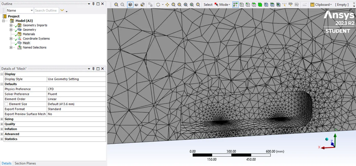
For the first case, we have used the default mesh size of 413.6 mm.
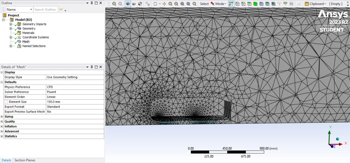
for the second case, we have used element size of 150mm.
Solver:-
Launching the fluent solver with 4 processes and double precision
We have replicated the k-omega modell as we used it previously
material used is air
inlet velocity
Creating a plane from Result -> Surface -> Plane
- After the physics part is done move to the solution part. Initialise the simulation first. click Initialize to initialize the boundary conditions. Hybrid method is selected before initialization. Click on Autosave to obtain a animation of the flow in the post results.
- Then run the calculation for a given number of iterations till the convergence is obtained. Depending upon the number of elements and model selected the time required for convergence varies. In the CFD module itself we can compute, measure, plot, animate, etc., if needed.
- After the solutions and calculations move to the result module to get different graphs, plots, contours, animations etc.,. Sectional views can be created if required.
Results:-
Case 1:-

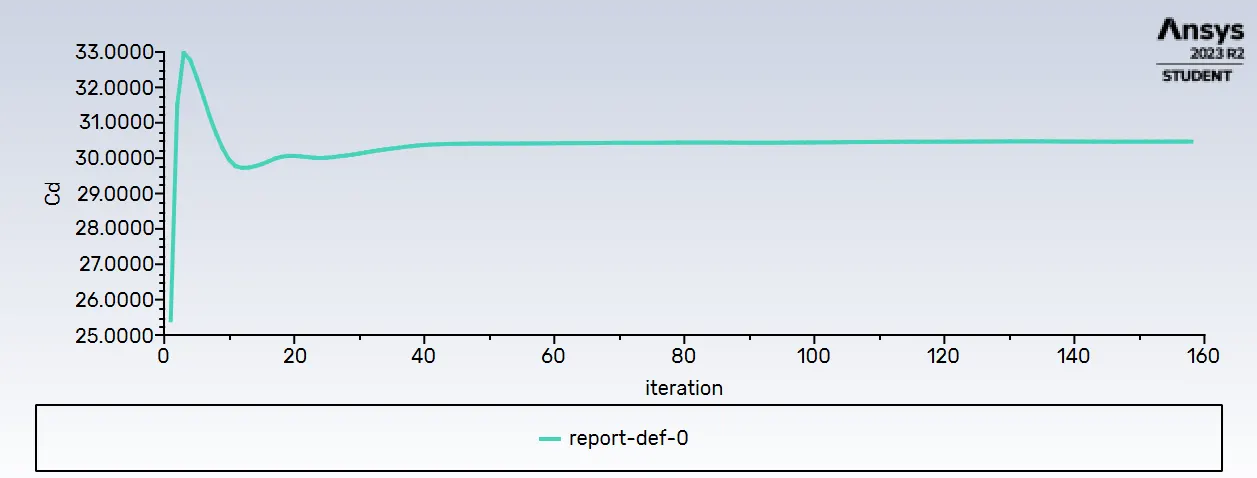
Case 2:-
Conclusion:-
- The grid independency test is carried out to demonstrate the variation of the result with respect to the accuracy of the mesh. The need for a good quality mesh to achieve an accurate result.
- The need of choice of Y+ according to application and quality of result need to attain by calculating the y value. The value of the coefficient of drag primarily depends upon the accurate value of Y+ in such cases grid independency test plays an important role.
- In the boundary layer separation, the need of the correct location of the separation point while designing for the vehicle.
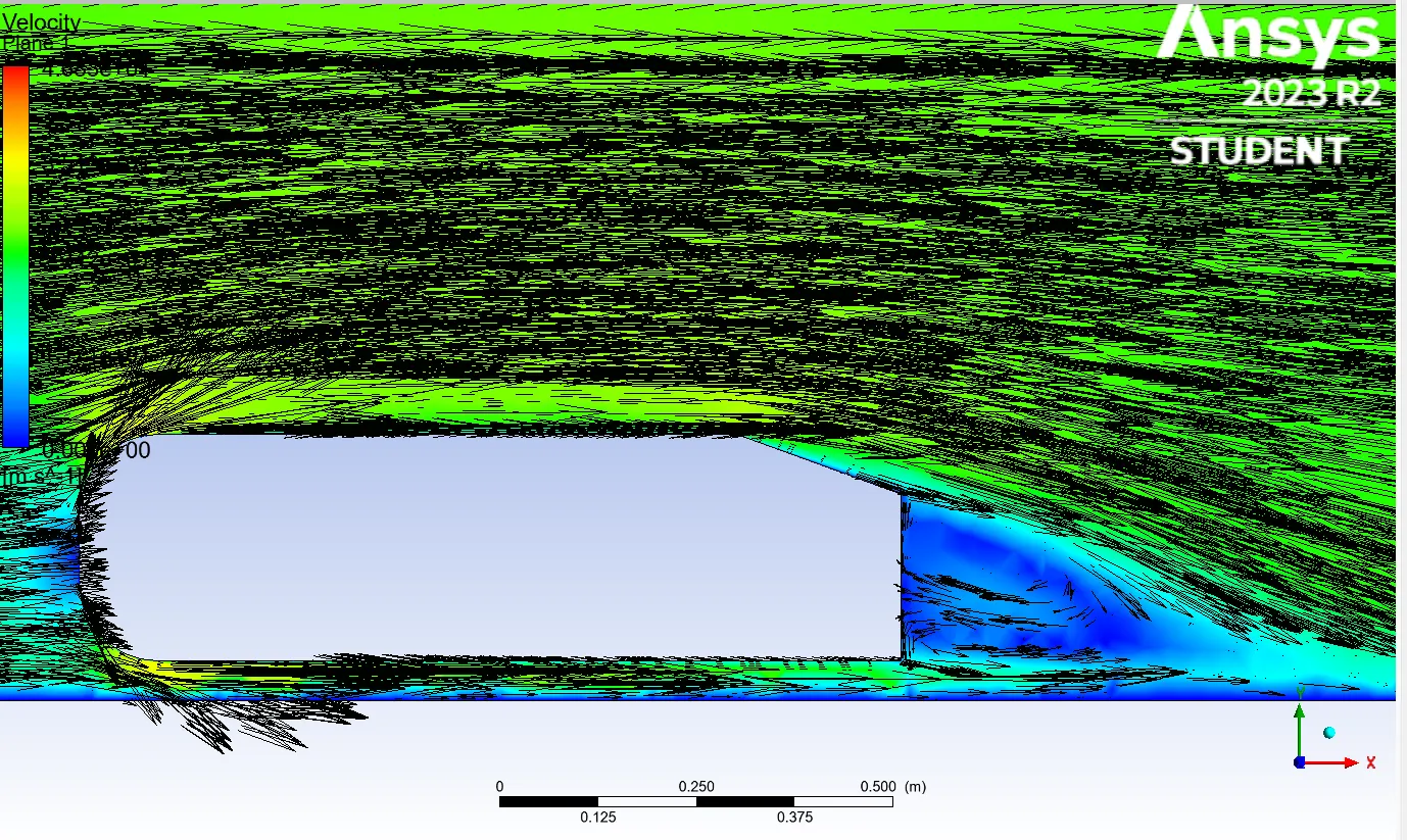
- The negative pressure in the wake region is primarily because there is no flow in that region. This can be further attributed to various factors such as separation and recirculation which is evident from the vector plot near the wake region.
- The point of separation occurs at the rear end of the vehicle, the separation occurs beyond this point where it can be observed that the flow recirculates and attaches it to the boundary layer.